Solar inverter for an extended insolation range and operating method

Active Publication Date: 2013-03-14
SMA SOLAR TECH AG
View PDF8 Cites 8 Cited by
  • Summary
  • Abstract
  • Description
  • Claims
  • Application Information

AI Technical Summary

Benefits of technology

The invention is a method for operating an inverter system for a photovoltaic solar plant. The method includes using an energy-storage device that can receive energy from the solar generator. The system detects the insolation conditions at the solar generator and, if there are peaks that exceed the maximum usable insolation, it initiates the transfer of energy from the solar generator to the energy storage device. This allows the inverter to operate at its maximum performance level. The technical effect of this method is improved efficiency of solar energy utilization and reduced energy wastage during periods of low insolation.

Problems solved by technology

However, the converters are usually not designed for the whole light radiation range.
However, weather conditions where the insolation values are higher so that the solar generator produces energy, which the conventionally dimensioned inverter can not accommodate, will also occur.
However, because the under-dimensioned inverter can not accommodate the excess energy yield, it keeps the operating point at values corresponding to its performance maximum whenever the maximum energy yield exceeds the capacity of the inverter.
As a result, part of the energy the solar generator could deliver is not utilized and is lost.
Such a set-up however has several disadvantages: First, as mentioned earlier, the inverter becomes more expensive with increasing size and capacity.
Second, under normal operation with partial load, for example at 10% of the generator rated energy output, the conversion efficiency is detrimentally affected.
Finally, a network or consumer which could accept the peak energies is often not available.

Method used


Image

  • Solar inverter for an extended insolation range and operating method
  • Solar inverter for an extended insolation range and operating method
  • Solar inverter for an extended insolation range and operating method

Examples


Embodiment Construction

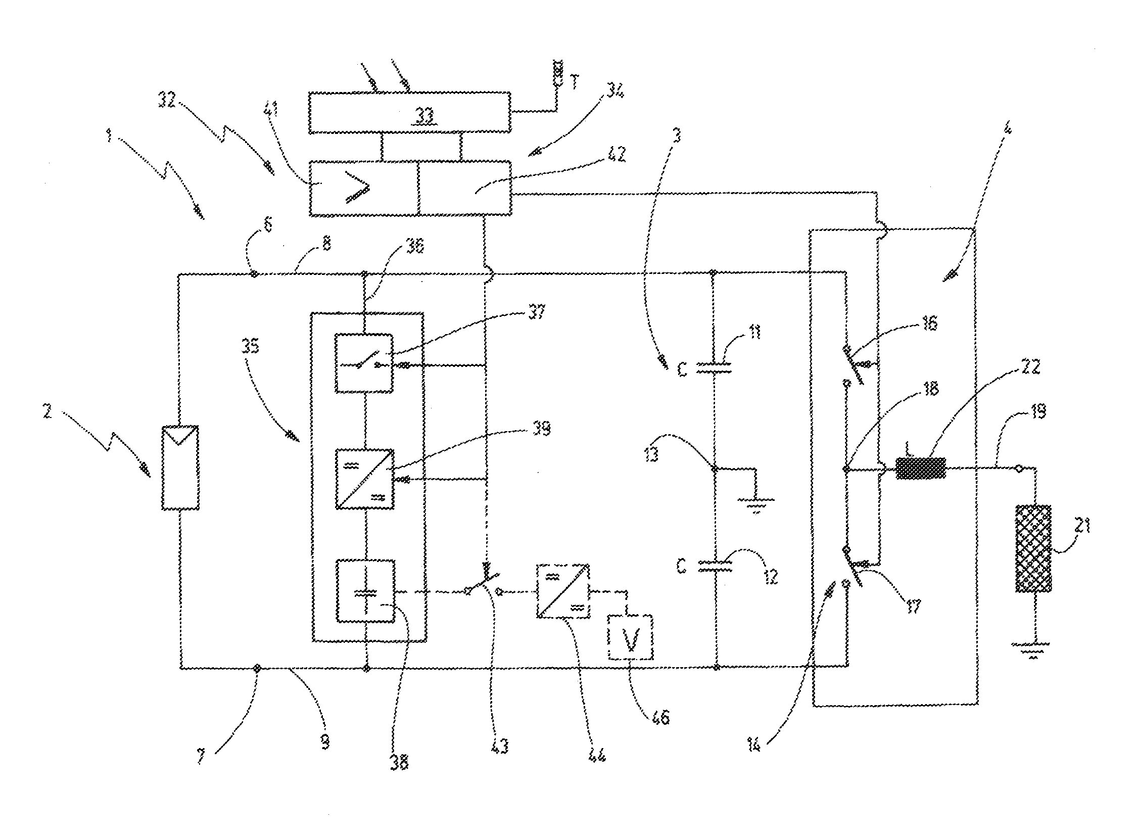
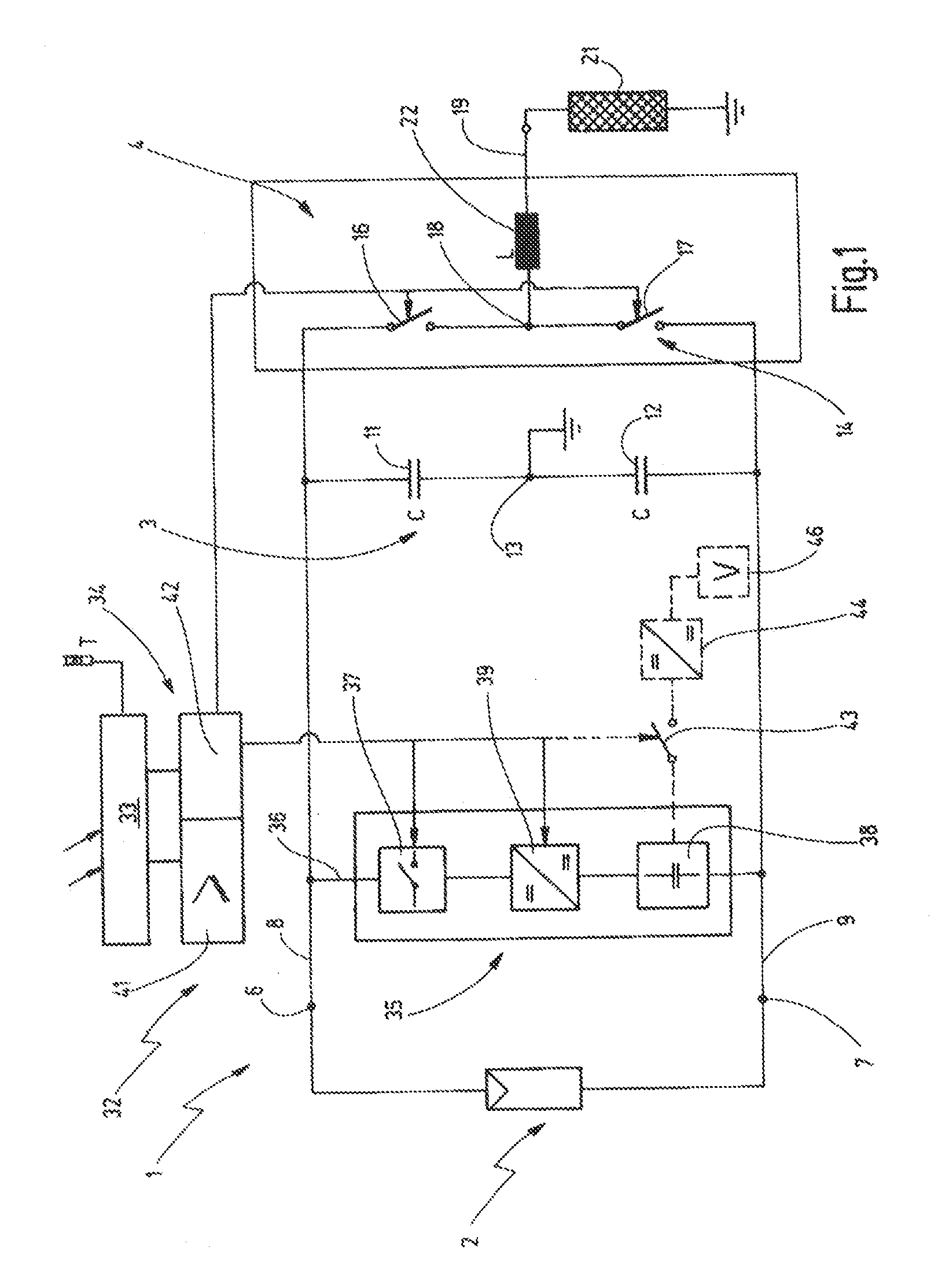
[0037]FIG. 1 shows an inverter system according to the invention which is provided for a photovoltaic solar panel for generating an AC voltage from a DC voltage. To this end, the shown inverter system 1 includes in a known way a solar generator 2, an intermediate circuit 3 connected to the solar generator, and an inverter 4 connected to the intermediate circuit.

[0038]The solar generator 2 comprises one or several solar modules, not shown, which convert insolating light into electrical energy. The solar generator 2 has electrical connections which are connected to a positive and a negative DC voltage connector 6, 7 of the inverter system 1. From the DC connectors 6, 7, DC voltage branches 8, 9 extend to the intermediate circuit 3 and to the inverter 4.

[0039]The intermediate circuit 3 in this case consists of two capacitors 11, 12 which are connected in series between the DC voltage branches 8, 9. The capacitors 11, 12 preferably have the same size so that they are both subjected to t...


PUM


Abstract

An inverter system (1) for a photovoltaic solar installation for generating an AC voltage from a DC voltage of a solar generator (2) is provided which includes an additional energy storage device (38) which is arranged in an energy transfer path that can be activated when needed. A control arrangement (31, 39) for monitoring and controlling the operation of the inverter system (1) is designed to detect short-term energy peaks of the insolation at the solar generator and, upon a presence of insolation peaks, to activate the energy transfer path (36) in order to cause a transfer of energy from the solar generator (2) to the energy storage device (38). Also a method for the operation of an inverter system for a photovoltaic solar installation for the utilization of insolation peaks at the solar generator is disclosed

Description

CROSS-REFERENCE TO RELATED APPLICATION[0001]This is a continuation-in-part application of pending international application PCT / EP2011 / 054560 filed Mar. 24, 2011 and claiming priority of German Patent Application No. 10 2010 016 138.1 filed Mar. 25, 2010.BACKGROUND OF THE INVENTION[0002]The invention resides in a solar converter for a photovoltaic solar system and an operating method therefore, in particular a solar inverter with a corresponding operating method for an extended insolation value range.[0003]Converter systems for photovoltaic solar plants for connection to a solar energy generator and to convert the DC voltage of the solar generator to a single or multiphase AC voltage are known in various configurations. In a common configuration they include an intermediate circuit, which is to be connected to the solar generator and one or several capacitors for storing energy, possibly a voltage amplifier arranged between the solar generator and the intermediate circuit to bring t...

Claims


Application Information

Patent Timeline
IPC IPC(8): H02J1/00
CPCH02J3/383Y02E10/563Y02E10/566H02J7/35H02J2300/24H02J3/381Y02E10/56
Inventor HANTSCHEL, JOCHEN
Owner SMA SOLAR TECH AG
Why Eureka
Try Eureka