Power supply device

Active Publication Date: 2013-03-14
PANASONIC INTELLECTUAL PROPERTY MANAGEMENT CO LTD
View PDF3 Cites 2 Cited by
  • Summary
  • Abstract
  • Description
  • Claims
  • Application Information

AI Technical Summary

Benefits of technology

[0011]According to the power supply device of the present invention, when the residual capacity of the rechargeable battery becomes less than a predetermined threshold value, the switching element is turned off to stop power supply from the rechargeable battery to the residual capacity detecting means. This makes it possible to reduce power consumption. Further, even if the power supply to the residual capacity detecting means is stopped, the rechargeable battery reaches a state of full charge when the value of the battery voltage has become a value lower than a peak value after the value of the battery voltage passes the peak value, if the charging of the rechargeable battery is started when the rechargeable battery has a residual capacity less than the predetermined threshold value. Further, when the value of the battery voltage of the rechargeable battery becomes a value lower than the peak value after the value of the battery voltage passes the peak value (i.e. when the rechargeable battery reaches the state of full charge), the charge control means stops charging the rechargeable battery. Thus, overcharging of the rechargeable batt

Problems solved by technology

However, these conventional power supply devices have problems as described below. FIG. 8 is a graph showing variation with time of battery capacity in a conventional power supply device without a residual capacity detection function, for explaining the problem of overcharging.
Thus, the method of detecting the peak value of the battery voltage to detect a state of full charge as described above cannot de

Method used


Image

  • Power supply device
  • Power supply device
  • Power supply device

Examples


Example

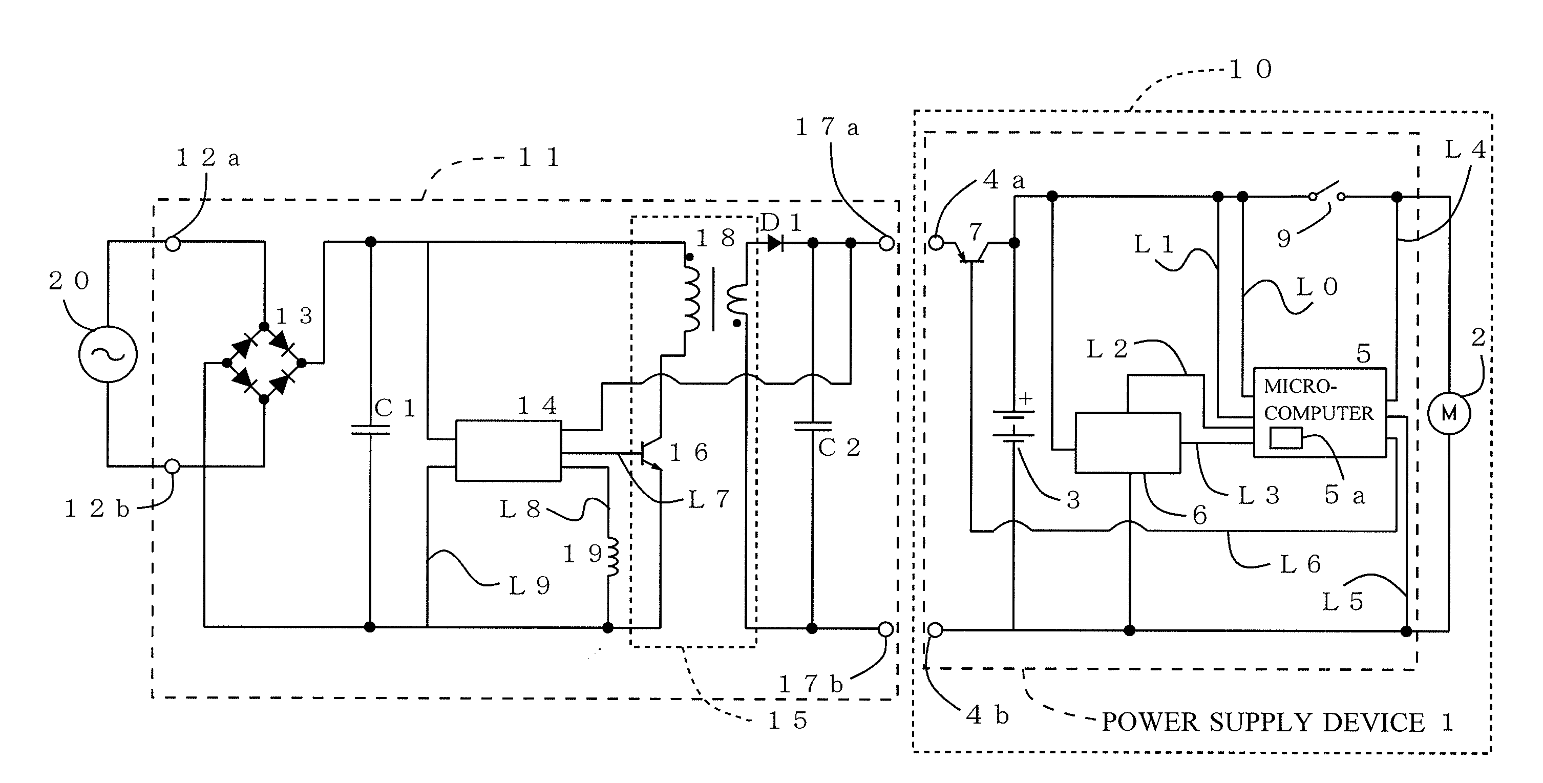
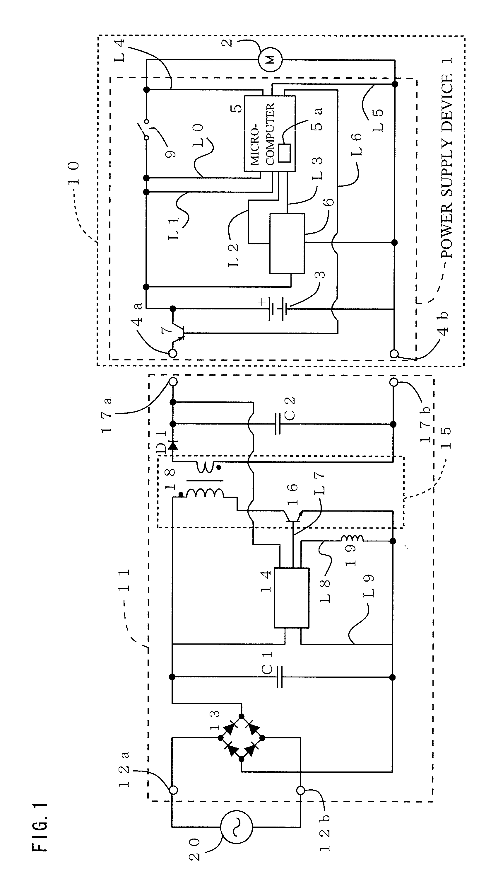
[0031]Embodiments of the present invention, as best mode for carrying out the invention, will be described hereinafter with reference to the drawings. The present invention relates to a power supply device. It is to be understood that the embodiments described herein are not intended as limiting, or encompassing the entire scope of, the present invention. FIG. 1 is a schematic circuit diagram, partially in block form, of a shaver body 10 (claimed “electrical device body”) including a power supply device according to an embodiment of the present invention, and an adapter 11 to be connected to the shaver body 10 for charging. The power supply device 1 is used for and integrally combined with the shaver body 10 which includes a motor 2 (claimed “load”).

[0032]The power supply device 1 comprises a rechargeable battery 3 for supplying power to the motor 2, and charge terminals 4a, 4b electrically connected to the rechargeable battery 3. The rechargeable battery 3 is a nickel metal hydride...


PUM


Abstract

Provided is a power supply device integrally combined with an electrical device body including a motor, comprising a rechargeable battery for supplying power to the motor, a microcomputer for detecting a residual capacity and a battery voltage of the battery, and a switching element provided between the battery and the microcomputer. The microcomputer stops charging the battery when the detected residual capacity has become 100%, and when the detected value of the battery voltage has become lower than a peak value after the value of the battery voltage passes the peak value, making it possible to prevent overcharging of the battery. The microcomputer also controls to turn off the switching element to stop the power supply from the battery to the microcomputer when the residual capacity becomes less than a predetermined threshold value, making it possible to reduce power consumption.

Description

BACKGROUND OF THE INVENTION[0001]1. Field of the Invention[0002]The present invention relates to a power supply device comprising a rechargeable battery for supplying power to a load of a motor, a lamp or the like.[0003]2. Description of the Related Art[0004]In a power supply device comprising a rechargeable battery for supplying power to a load of a motor, a lamp or the like, it is necessary to prevent overcharging of the rechargeable battery so as to prevent overheating and explosion of the battery. Thus, conventionally, a microcomputer in many such power supply devices is provided with a function to detect a residual capacity of the rechargeable battery (residual capacity detection function) so as to stop (end) charging the rechargeable battery when the microcomputer detects that the residual capacity has become 100% (full charge). However, in the full charge detection method using the residual capacity detection function, it is required to continuously operate the microcomputer ...

Claims


Application Information

Patent Timeline
IPC IPC(8): H02J7/00H02J7/02G01R31/36H02J7/04
CPCH02J7/0078H02J7/045H02J7/044H02J7/0081H02J7/007184H02J7/00716H02J7/04
Inventor WATANABE, KAZUNORIASAKAWA, KOJI
Owner PANASONIC INTELLECTUAL PROPERTY MANAGEMENT CO LTD
Why Eureka
Try Eureka