Display device
a technology of display device and display element, applied in the field of display device, can solve the problems of increasing variation, inability of conventional display device to compensate for individual light-detecting elements, etc., and achieve the effect of wide dynamic range of light sensors
- Summary
- Abstract
- Description
- Claims
- Application Information
AI Technical Summary
Benefits of technology
Problems solved by technology
Method used
Image

Examples
embodiment 1
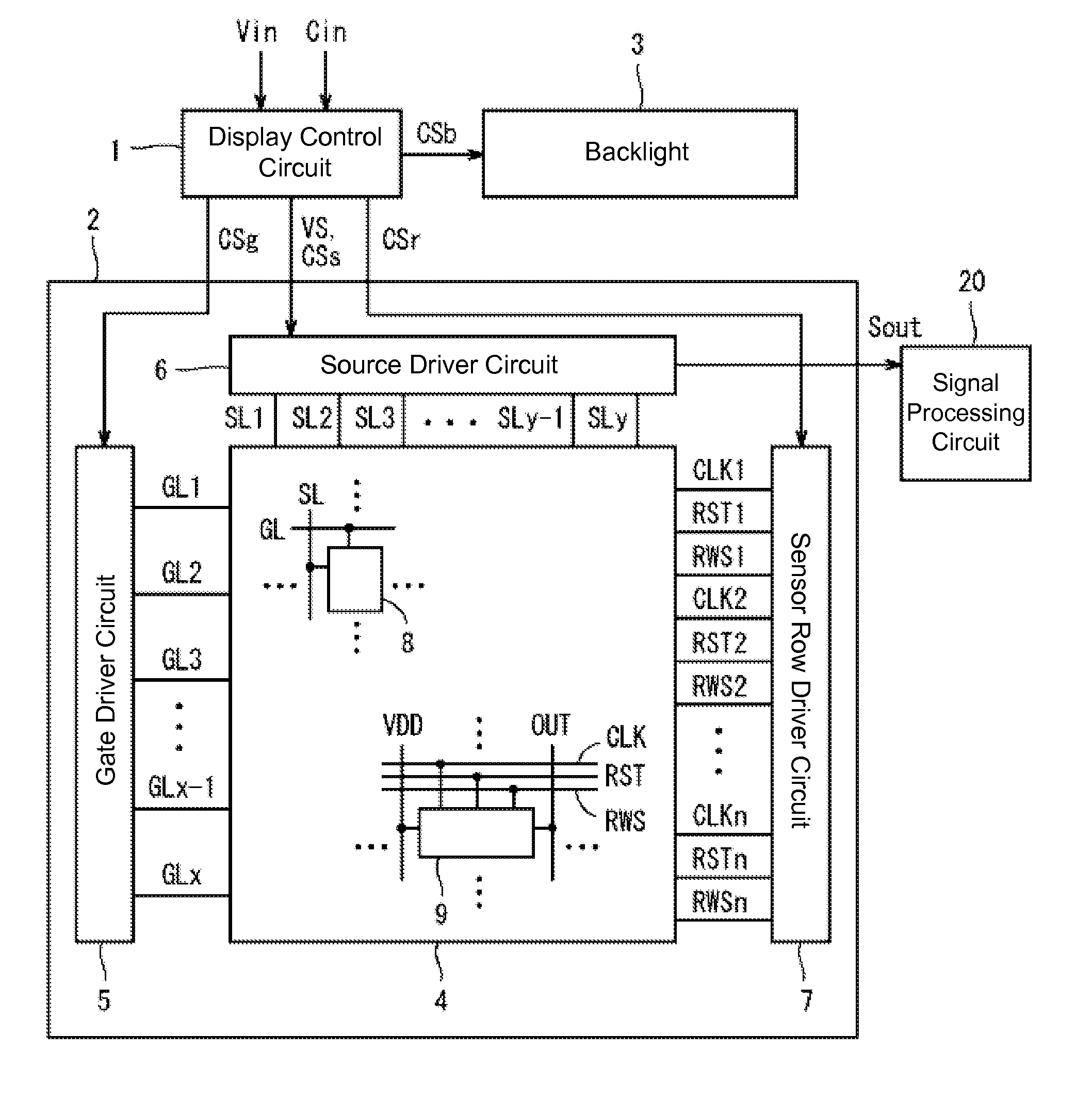
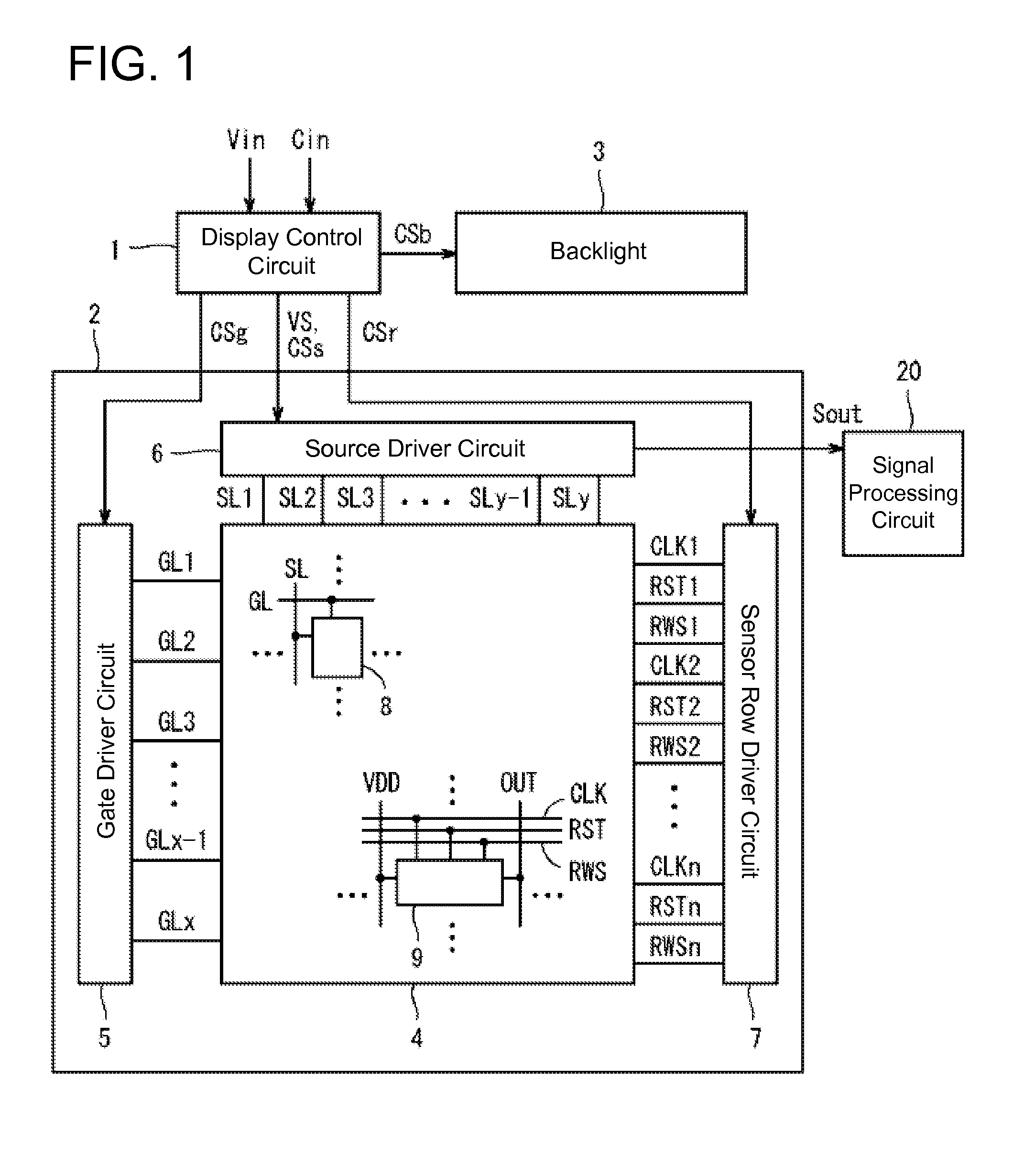
[0092]FIG. 1 is a block diagram showing the configuration of a display device according to Embodiment 1 of the present invention. The display device shown in FIG. 1 includes a display control circuit 1, a display panel 2, and a backlight 3. The display panel 2 includes a pixel region 4, a gate driver circuit 5, a source driver circuit 6, and a sensor row driver circuit 7 (sensor driver circuit). The pixel region 4 includes a plurality of display pixel circuits 8 and a plurality of sensor pixel circuits 9. This display device has a function of displaying images on the display panel 2, and a function of detecting the light entering the display panel 2. Hereinafter, x is an integer of at least 2, y is a multiple of 3, m and n are even numbers, and the display device frame rate is 60 frames / sec.
[0093]To the display device shown in FIG. 1, an image signal Vin and a timing control signal Cin are supplied from outside. Based on these signals, the display control circuit 1 outputs an image ...
example 1
Correction Example 1
[0161]In correction example 1, the corrected light sensor signal level R′ is expressed as below, where “B” is the light sensor signal level acquired from the second pixel circuit 10b in the sensor driving mode and “R” is the light sensor signal level acquired from the first pixel circuit 10a in the sensor driving mode.
R′=(R−Ofst_on)−(B−Ofst_off)
[0162]With this correction, the offset of the first pixel circuit 10a and the second pixel circuit 10b are cleared, and accurate sensor outputs can be obtained. An additional benefit of the offset elimination is that it expands the dynamic range of the sensor output.
Correction Example 2
[0163]In correction example 2, in the first correction data acquisition mode, a read-out signal having zero amplitude is supplied to obtain a gain correction light sensor signal level W1st, and in the second correction data acquisition mode, a read-out signal having zero amplitude is supplied to obtain a gain correction light sensor signal l...
example 2
[0169]In Example 2, as shown in FIG. 16, the first correction data Ofst_on and the second correction data Ofst_off are updated when the sensor drive mode of the display device switches from the normal mode to the standby mode.
[0170]In the example shown in FIG. 16, when the coordinates detection process starts with the normal sensor cycle (step S201), on the display panel 2 side, the sensor row driver circuit 7 reads out the sensor outputs in the sensor driving mode (step S206). At the same time, on the recognition engine side, which includes the signal-processing circuit 20, whether a touch by a finger or the like is recognized or not is determined based on the sensor outputs read out in the step S206 (step S202). Here, if a touch is recognized, (“Yes” in step S202), the frame count is cleared (step S203) and the process returns to step S202. On the other hand, if no touch is recognized in step S202, the frame count is incremented by one (step S204), and the result is compared with ...
PUM
 Abstract
Description
Claims
Application Information
 - R&D
- Intellectual Property
- Life Sciences
- Materials
- Tech Scout
- Unparalleled Data Quality
- Higher Quality Content
- 60% Fewer Hallucinations
Browse by: Latest US Patents, China's latest patents, Technical Efficacy Thesaurus, Application Domain, Technology Topic, Popular Technical Reports.
© 2025 PatSnap. All rights reserved.Legal|Privacy policy|Modern Slavery Act Transparency Statement|Sitemap|About US| Contact US: help@patsnap.com