Converter Cell For Cascaded Converters And A Control System And Method For Operating A Converter Cell

a converter cell and control system technology, applied in the direction of dc-ac conversion without reversal, television systems, etc., can solve the problems of additional hardware, inability to ensure fault-free operation of such components, and cost for society as well as power providers, so as to reduce the risk of undesired damage, reduce the risk of peak current, and reduce the effect of space occupation

Inactive Publication Date: 2013-03-14
ABB RES LTD
View PDF9 Cites 34 Cited by
  • Summary
  • Abstract
  • Description
  • Claims
  • Application Information

AI Technical Summary

Benefits of technology

[0011]By the cascaded converter and method of by-passing a converter cell is achieved that a faulty converter cell can be by-passed even without providing power to any gate drive unit in the cell. Furthermore, the by-passing mechanism provided by the cascaded converter and the method of by-passing a converter cell can be achieved without the use of any additional hardware. Thus, a simple and space efficient way of providing by-passing possibilities to a cascaded converter can be achieved by the present technology.
[0012]In one embodiment, the converter cell further comprises a reactor connected in series between the cell capacitor and a phase leg, in order to limit the peak current upon short-circuiting of the cell capacitor. Hereby, a too rapid heating of the components of the phase leg 120 upon short-circuiting of the cell capacitor can be avoided, thereby reducing the risk of undesired damage. A clamping circuit connected so as to limit the voltage

Problems solved by technology

In such applications, it is important that the down time of the converters is reduced to a minimum, since failure of a converter may result in power outages, which can be costly for society as well as for the power provider.
Despite efforts to improve the life time and cycling capability of electronic components, fault free operation of such componen

Method used


Image

  • Converter Cell For Cascaded Converters And A Control System And Method For Operating A Converter Cell
  • Converter Cell For Cascaded Converters And A Control System And Method For Operating A Converter Cell
  • Converter Cell For Cascaded Converters And A Control System And Method For Operating A Converter Cell

Examples


Embodiment Construction

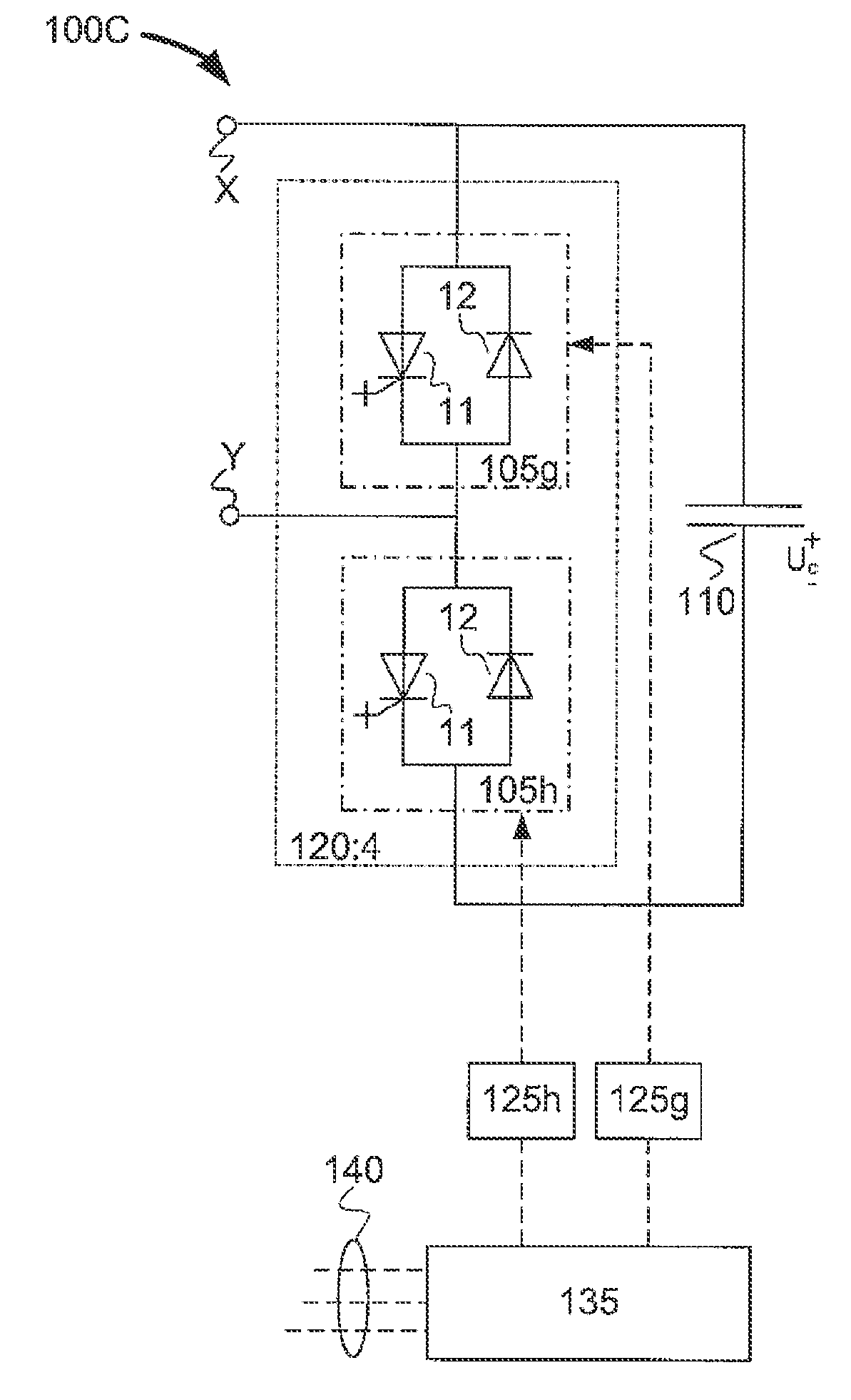
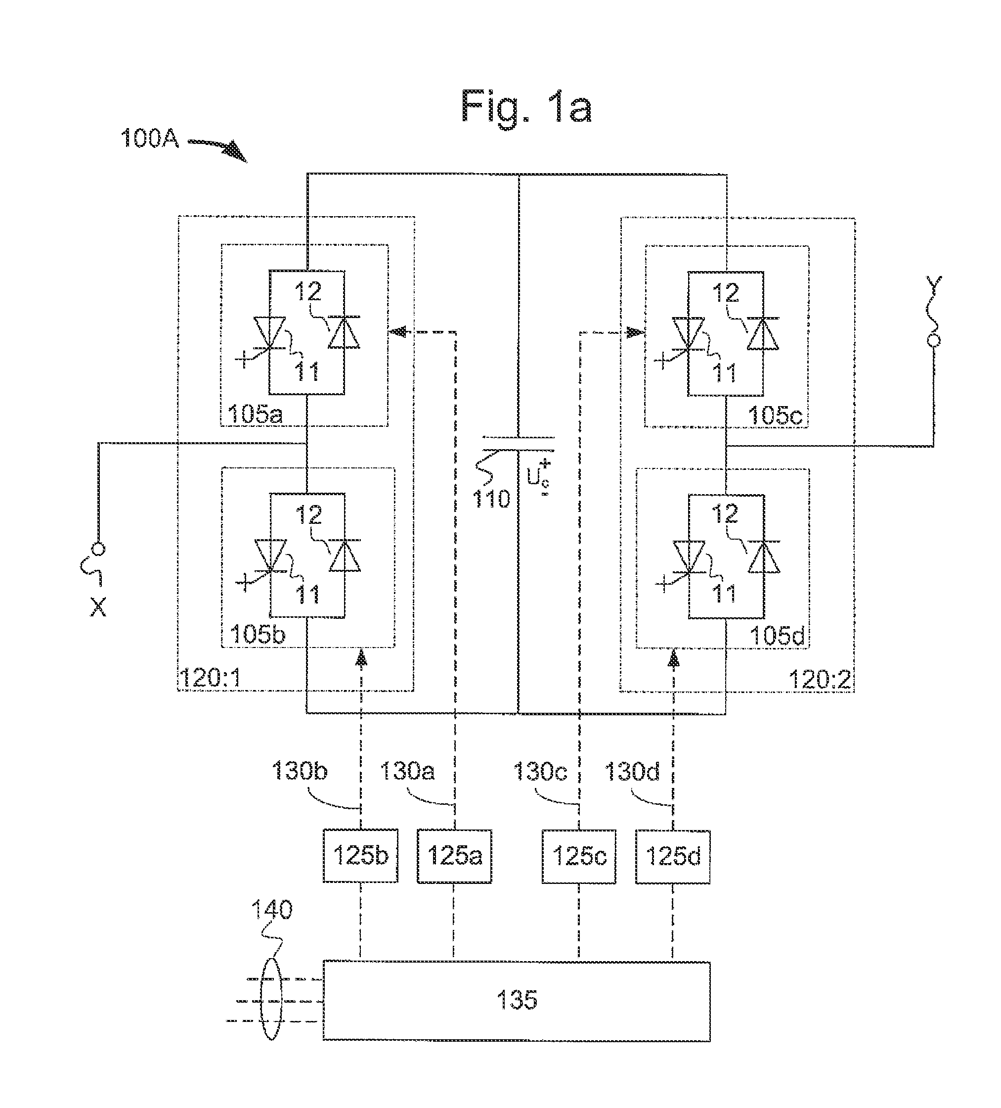
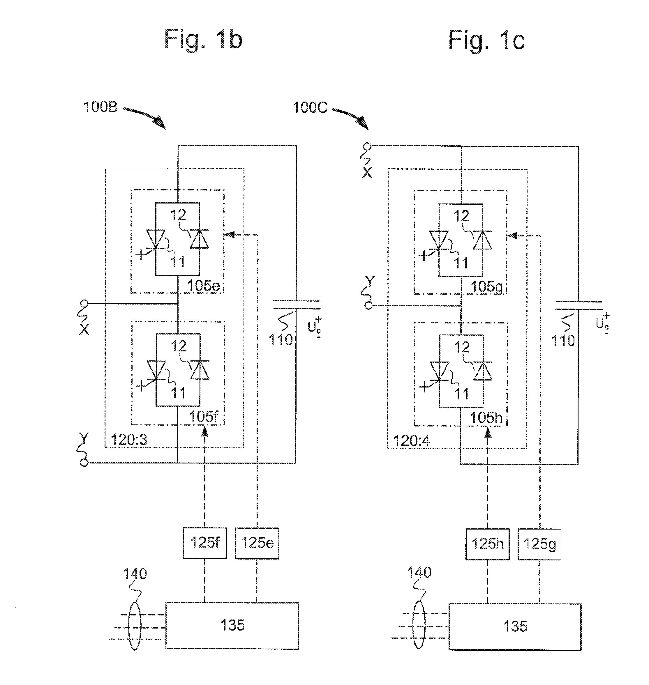
[0034]FIG. 1a illustrates an example of an embodiment of a converter cell 100A, which could for example be used in a cascade converter as shown in FIG. 3a. Converter cell 100A comprises four electric valves 105a-d which are configured to be able to conduct current in both directions and block voltage in one direction. An electric valve 105a-d of FIG. 1a includes a unidirectional switch 11, or switch 11 for short, and an anti-parallel diode 12, where the unidirectional switch 11 can be controlled to switch off, as well as to switch on. The four valves 105a-d are arranged in a full-bridge configuration (also referred to as an H-bridge configuration) comprising two phase legs: Phase leg 120:1, wherein valve 105a and valve 105b are series connected, and phase leg 120:2, wherein valves 105c and valve 105d are series connected. Within a phase leg 120:1 or 120:2, the valves are connected to be able to block voltage in the same direction. The two phase legs 120:1 and 120:2 are connected in ...


PUM


Abstract

A cascaded electric power converter and a method of operating a cascaded electric power converter are disclosed. The cascaded converter includes: a converter cell including a cell capacitor and at least one phase leg having at least two electric valves, the at least one phase leg being connected in parallel to the cell capacitor; and a control system for controlling the switching of the electric valves of the at least one phase leg. The control system is configured to, upon detection of a need to by-pass the converter cell, control the switching of the electric valves in a manner so that the cell capacitor is short circuited via a phase leg, so as to obtain a current surge through the phase leg, thereby creating a permanent current path through the converter cell.

Description

CROSS-REFERENCE TO RELATED APPLICATIONS[0001]The present application is a continuation of pending International patent application PCT / EP2010 / 053576 filed on Mar. 18, 2010 which designates the United States and the content of which is incorporated herein by reference.FIELD OF THE INVENTION[0002]The present invention relates to the field of power electronic converters, and in particular to cascaded power electronic converters.BACKGROUND OF THE INVENTION[0003]Power electronic converters including semiconductor valves are widely used to change the character of electrical energy by means of controlling the voltage, current and / or frequency. Power electronic converters are for example increasingly used in power transmission applications, such as in HVDC transmission systems or in static VAR compensation systems for utility or industry grids.[0004]In such applications, it is important that the down time of the converters is reduced to a minimum, since failure of a converter may result in ...

Claims


Application Information

Patent Timeline
IPC IPC(8): H02M7/12
CPCH02M1/32H02M7/49B60L15/007H02M2007/4835H02M2001/325H02M7/797Y02T10/64H02M1/325H02M7/4835H02J2003/365H02M1/007
Inventor NORRGA, STAFFANDIJKHUIZEN, FRANSJONSSON, TOMASSETZ, THOMAS
Owner ABB RES LTD
Why Eureka
Try Eureka