Ultrasound bone imaging assembly

a technology of ultrasonic bone and assembly, which is applied in the field of ultrasonic bone imaging devices, can solve the problems of x-ray transillumination, health risks to the physician, and delay in securing the locking screws in place, and achieve the effect of reducing fractures

Inactive Publication Date: 2013-03-14
LASTER ZVI +4
View PDF2 Cites 1 Cited by
  • Summary
  • Abstract
  • Description
  • Claims
  • Application Information

AI Technical Summary

Benefits of technology

[0018]According to an aspect of some embodiments of the present invention there is provided a method for re

Problems solved by technology

In spite of the use of an IM jig to locate and drill the locking holes through the IM nail, there can be alignment problems that cause delays in securing the locking screws in place.
The resulting extended use of the C-arm increases the exposure time of the patient to harmful ionizing radiation which can jeopardize patient health.
Additionally, X-ray transillumination presents a health risk to the physician, whose hands must function under the X-ray beam during fracture alignment, reduction, IM nail placement, drilling locking holes, and placement of locking screws.
The many X-ray transillumination operations

Method used


Image

  • Ultrasound bone imaging assembly
  • Ultrasound bone imaging assembly
  • Ultrasound bone imaging assembly

Examples


Embodiment Construction

[0055]The present invention generally relates to ultrasound bone imaging assemblies and, more particularly, but not exclusively, to an ultrasound bone imaging assembly for use in conjunction with a fracture fixation system.

[0056]Before explaining at least one embodiment of the invention in detail, it is to be understood that the invention is not necessarily limited in its application to the details of construction and the arrangement of the components and / or methods set forth in the following description and / or illustrated in the drawings. The invention is capable of other embodiments or of being practiced or carried out in various ways.

[0057]Referring now to the drawings:

Ultrasound Fracture Reduction

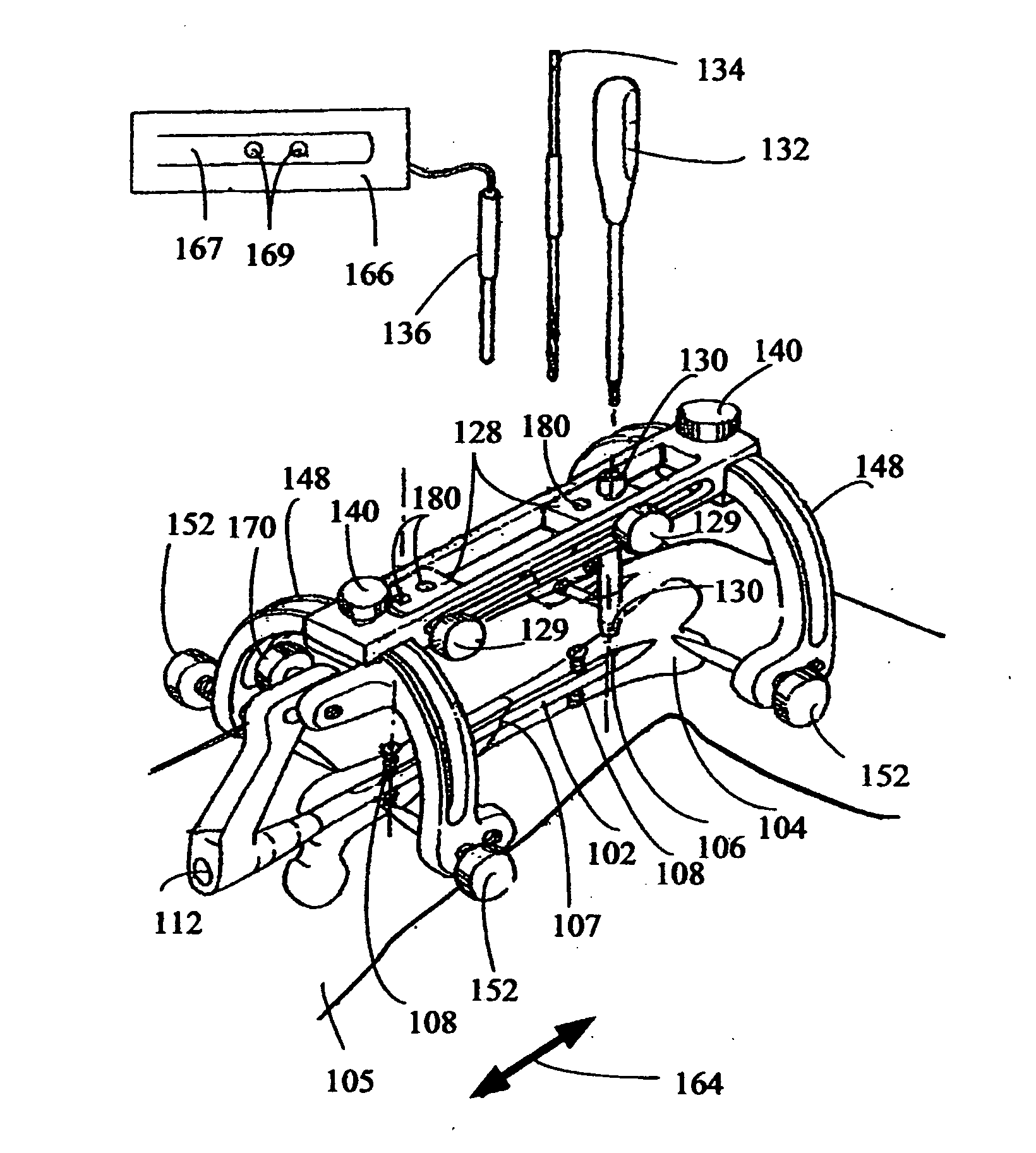
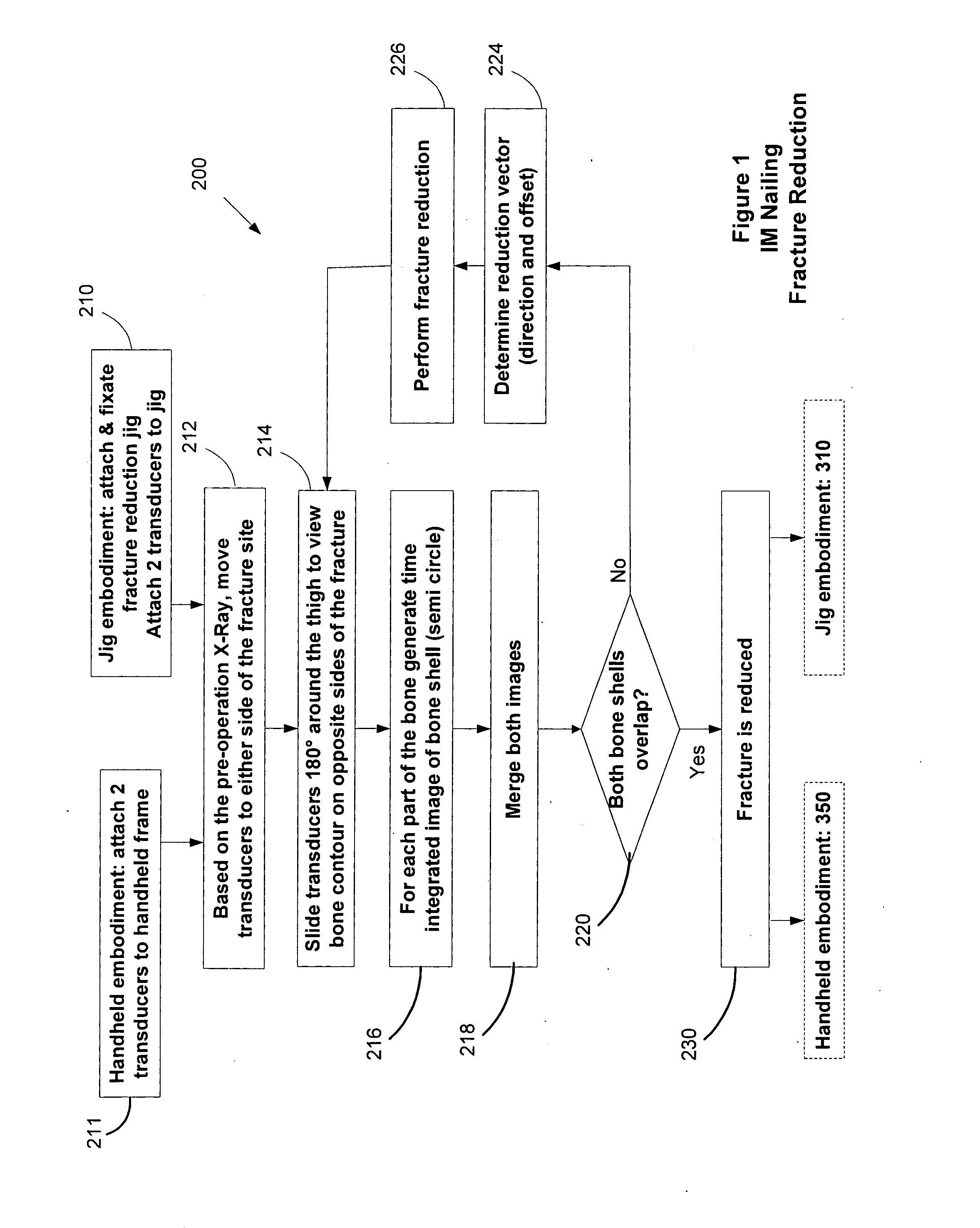
[0058]FIG. 1 shows an intramedullary nailing flow chart 200 wherein at a stage 210 a fracture reduction jig is attached proximate to the fractured bone and two fracture ultrasound transducers are placed in sliding jig holes.

[0059]Alternatively, at a stage 211, when using a handheld frac...


PUM


Abstract

A device for orienting a bone cutting tool with respect to a locking screw hole of an intramedullary nail inserted within a bone is provided. The device includes a device body which is configured with a cutting path for a cutting device and a distal end portion which is adapted for positioning against a surface of the bone. The device also includes an ultrasound probe holder which serves for aligning the cutting path with the screw locking feature using at least one ultrasound signal of at least one ultrasound probe attached to the device.

Description

FIELD OF THE INVENTION[0001]The present invention generally relates to ultrasound bone imaging devices and, more particularly, but not exclusively, to an ultrasound bone imaging assembly for use in conjunction with fracture fixation.BACKGROUND OF THE INVENTION[0002]Fracture reduction of a long bone may require alignment and reduction of the fracture using X-ray transillumination comprising, for example a C-arm X-ray system. A C-arm X-ray includes an X-ray source configured to be positioned on one side of a body portion of a subject and a detector configured to be positioned on a second side of the body portion. The C-arm is swiveled around the body portion in multiple axes to produce transillumination X-ray images.[0003]In a fractured long bone, for example the femur, fracture fixation may require using an intramedullary (IM) rod, alternatively referred to as an IM nail. In IM rod fixation of the femur, C-arm X-ray transillumination may be used to image the fractured bone portions d...

Claims


Application Information

Patent Timeline
IPC IPC(8): A61B8/08
CPCA61B8/0841A61B8/0875A61B8/4209A61B17/8866A61B17/1725A61B17/6441A61B17/1703
Inventor LASTER, ZVIWEISSBERG, ILANELDAR, ADILEVY, AVRAHAMELKAIM, DAVID
Owner LASTER ZVI
Why Eureka
Try Eureka