Filter element attachment, filter cartridge, and filter system

a filter element and filter cartridge technology, applied in the direction of membranes, filtration separation, separation processes, etc., to achieve the effects of increasing strength, reducing efficiency, and increasing reliability of sensors and internal devices

Active Publication Date: 2013-03-21
SARTORIUS STEDIM BIOTECH GMBH
View PDF12 Cites 52 Cited by
  • Summary
  • Abstract
  • Description
  • Claims
  • Application Information

AI Technical Summary

Benefits of technology

[0031]A plurality of sight glasses can be located at different areas of the filter housing for a variety of purposes. These include a sight glass that wraps around the length of the housing and/or along the circumference of the filter housing to observe bubbles during a reverse pressure leak test which can detect a leakage in the setup or filter membrane when filled with fluid. A macro lens camera with LED lights can be mounted onto a sight glass to detect/document filter cake layer formation and/or plugging. A thermal imaging camera can be used to view temperature fluctuations during the fluid flow of materials in the filter housing during filtration or in a reverse flow test with a warm fluid. A laser particle detector can be used to estimate the concentration/number of particles within a defined space or the density of the material inside of the filter housing during filtration. The sight glasses will also allow the user to observe conditions inside of the filter housing during processing.
[0032]The filter housing sight glass could also be utilized to transmit wireless power from an external power source located outside of the filter housing to an internal receiver of the filter element attachment used to power sensors, electronic components, and/or devices located within the interior of the filter housing. The internal receiver for an external power source can be centrally located or distributed to each individual electronic device. The use of the sight glass is especially useful for wireless power technologies where line of sight with the power receiving device is required. The sight glass could for example be used to transmit a laser as an external power source for use by internal sensors and/or devices. Wireless power using microwaves, visible light, lasers or other electromagnetic sources can be transmitted via an external power source to an internal receiver

Problems solved by technology

However, the filter cartridge itself is hidden in the filter testing device and an user of the filter te

Method used


Image

  • Filter element attachment, filter cartridge, and filter system
  • Filter element attachment, filter cartridge, and filter system
  • Filter element attachment, filter cartridge, and filter system

Examples


Embodiment Construction

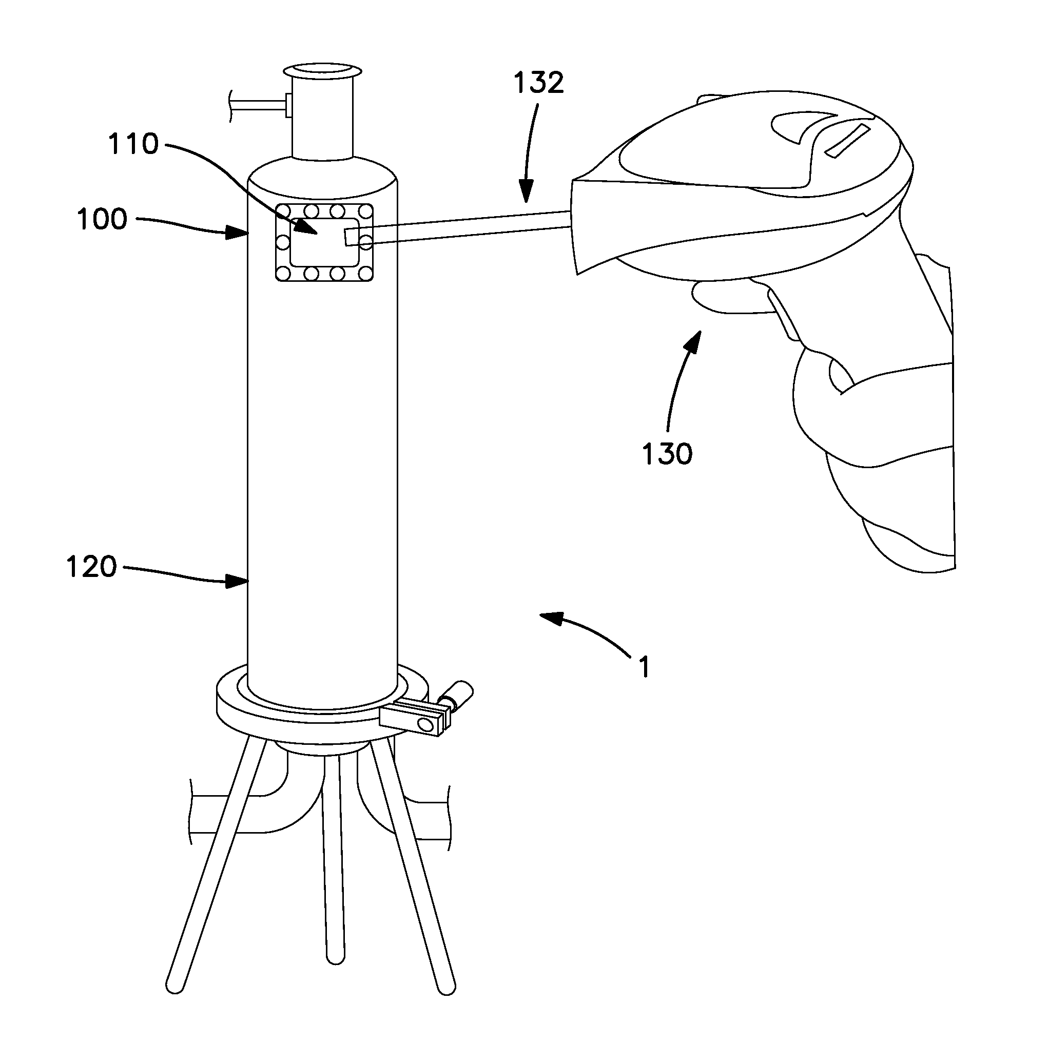
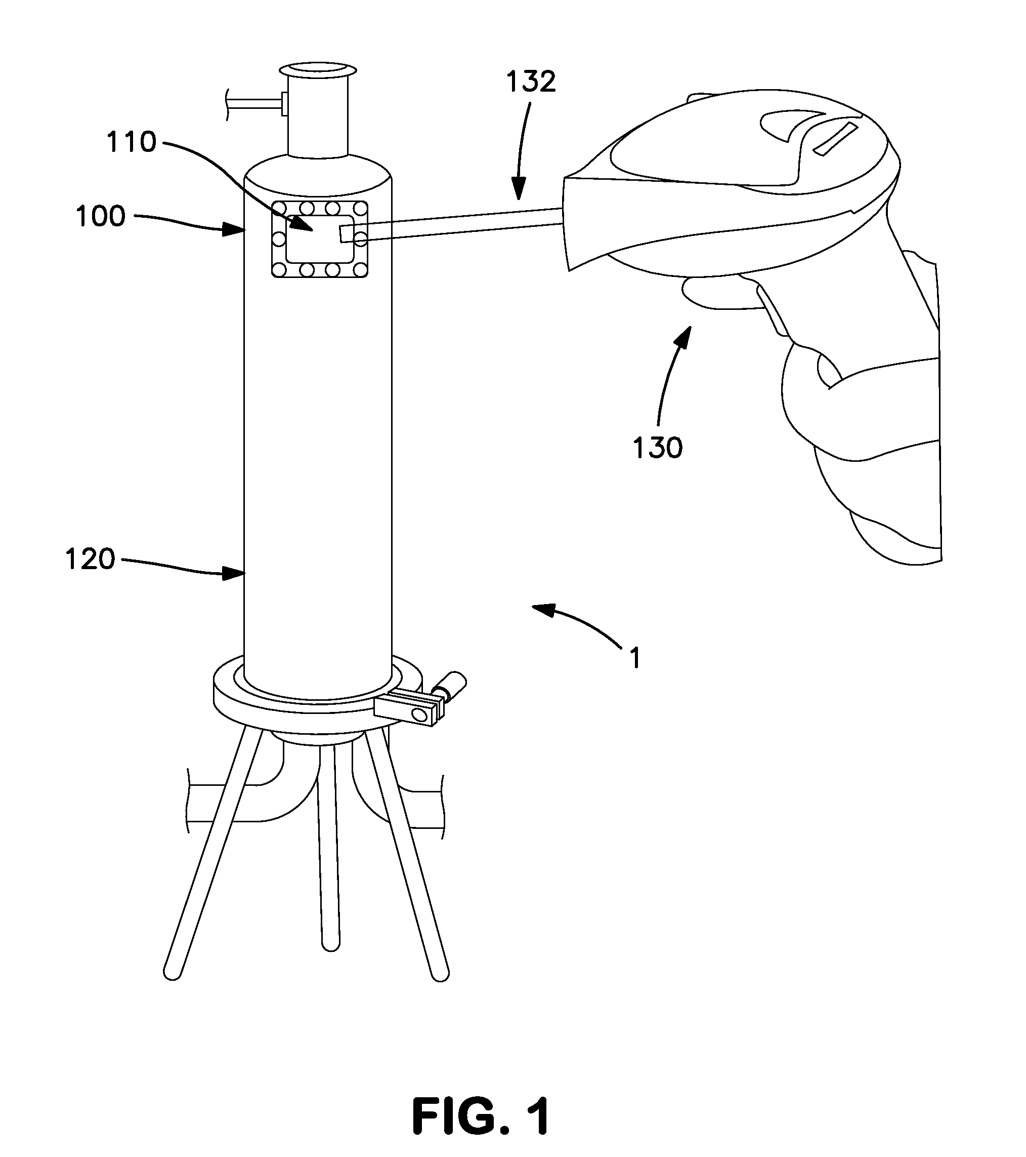
[0054]FIG. 1 shows a filter system 1 having a filter housing 120 with a wall made of metal, such as stainless steel in order to prevent corrosion. The filter housing may have a bell shape as shown in FIG. 1. A sight glass 100 is covering an aperture of the metal wall of the filter housing 120. Through the sight glass the top a filter cartridge loaded into the filter housing 120 can be observed. The filter cartridge comprises a filter element, such as a membrane filter, and a filter element attachment, which is mounted to top of the filter element. As can be seen in FIG. 1 the filter element attachment 110 adapter of the installed filter cartridge is visible through the sight glass. The filter element attachment 110 may comprise a two-dimensional barcode as a preferred display means 110. Since the barcode is visible through the sight glass 100, it can be scanned by a barcode scanner light beam 132 from an external barcode scanner 130 from the outside of the filter housing 120. Advant...


PUM

PropertyMeasurementUnit
Poweraaaaaaaaaa
Transparencyaaaaaaaaaa

Abstract

A filter element attachment is provided and is attachable to a filter element. The filter element attachment includes a housing for receiving at least a part of the filter element; at least one display configured to display information associated with the filter element. The filter element attachment may be associated with a corresponding filter cartridge and a filter system.

Description

BACKGROUND OF THE INVENTION[0001]1. Field of the Invention[0002]The present invention relates to improvements for controlling a filter system in use as well as a corresponding filter cartridge, which is used for filtering or which is under test, with respect to its permeability. Accordingly, the invention relates to the corresponding filter cartridge and a filter element attachment, which can be attached a filter element to form the filter cartridge.[0003]2. Description of the Related Art[0004]As it is known from document U.S. Pat. No. 4,384,474 A at least one membrane filter cartridge can be installed in a filter testing device in order to test the integrity of the membrane filter cartridge. The filter testing device comprises a sight glass which is arranged to observe gas bubbles in an outlet, when air pressure is applied to the filter cartridge and the air is leaking through an defective part of the membrane filter cartridge. However, the filter cartridge itself is hidden in the ...

Claims


Application Information

Patent Timeline
IPC IPC(8): B01D35/143B01D35/00
CPCB01D35/30B01D2201/52B01D2313/20B01D65/00B01D65/102B01D2201/56B01D2313/201B01D2313/2061B01D2313/205
Inventor MAGGIORE, FRANKVANWORMER, LEON
Owner SARTORIUS STEDIM BIOTECH GMBH
Why Eureka
Try Eureka