Motor Drive Apparatus

a motor drive and motor technology, applied in the direction of control/drive circuits, solid-state devices, cooling/ventilation arrangements, etc., can solve the problem that the motor drive apparatus cannot be sufficiently downsized

Active Publication Date: 2013-03-21
HITACHI ASTEMO LTD
View PDF10 Cites 13 Cited by
  • Summary
  • Abstract
  • Description
  • Claims
  • Application Information

AI Technical Summary

Benefits of technology

[0004]However, in the above previously-proposed motor drive apparatus, a heat-radiating surface of a semiconductor switching element which has a largest surface area of the semiconductor switching element is in contact with a heat spreader abutting on a surface of a cover member which faces a control substrate. That is, the heat spreader is interposed between the heat-radiating surface of the semiconductor switching element and the cover member to radiate heat of the semiconductor switching element.

Problems solved by technology

Hence, there is a problem that the motor drive apparatus cannot be sufficiently downsized.

Method used


Image

  • Motor Drive Apparatus
  • Motor Drive Apparatus
  • Motor Drive Apparatus

Examples


first embodiment

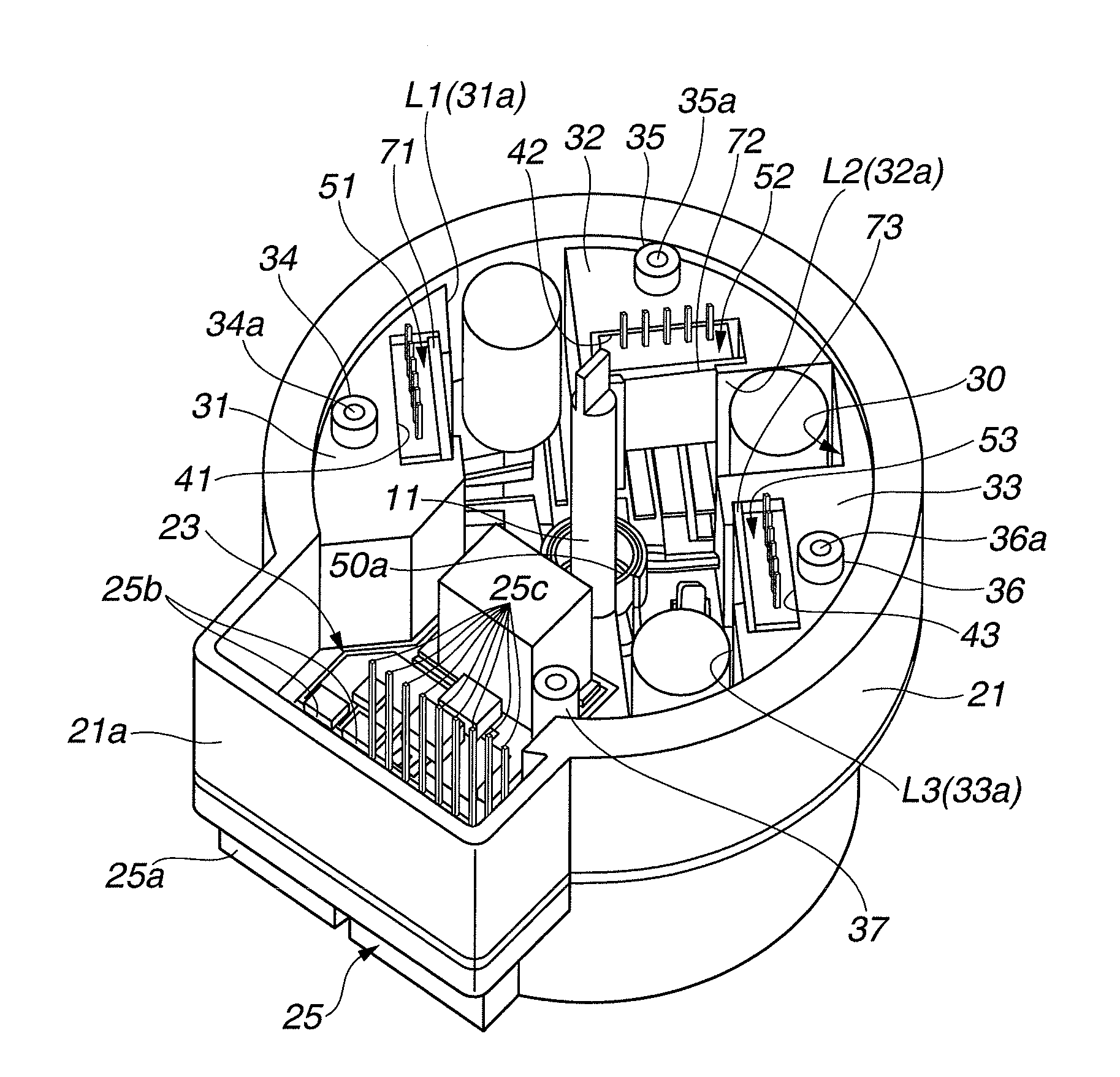
[0052]According to the motor drive apparatus in the first embodiment, the power module 51-53 is arranged on the metallic substrate 50 to cause major surfaces of the power module 51-53 to be perpendicular to the control substrate 24. Moreover, the heat-radiating surface 61a-63a having the maximum area among the module main body 61-63 of the power module 51-53 is made to be in contact with the heat-receiving surface 41a-43a constituted inside the heat sink 31-33. That is, the heat-radiating surface 61a-63a is not in contact with a surface of the metallic substrate 50 as an earlier technology. Therefore, an area of the metallic substrate 50 which is occupied (contacted) by the power modules 51 to 53 can be reduced. That is, an area (i.e., dimensions in a plane perpendicular to the axial direction of motor 10) of the substrate receiving portion 30 of the ECU housing 21 can be reduced resulting in a downsizing of the ECU 20.

[0053]The power modules 51 to 53 are held under a state where th...

second embodiment

[0058]In the second embodiment, a pair of module retaining members 710a and 710b are provided in the module receiving portion 41 instead of the module retaining member 71. That is, one module retaining member 710a is inserted (pushed with force) into a clearance (space) C2 formed between the lateral surface 61b of the power module 51 and the lateral support surface 41b of the module receiving portion 41. At the same time, another module retaining member 710b is inserted (pushed with force) into a (another) clearance C2 formed between the lateral surface 61c of the power module 51 and the lateral support surface 41c of the module receiving portion 41.

[0059]The pair of module retaining members 710a and 710b are formed basically to fill the both clearances C2. A maximum value of an X-axis-directional width X1 of each module retaining member 710a, 710b is set to be slightly larger than an X-axis-directional width X2 of the clearance C2. Moreover, a predetermined tapering surface 710c is...

fourth embodiment

[0069]Also in this fourth embodiment, the module main body 61 of the power module 51 can be held and fastened by the pair of module retaining members 710a′ and 710b′. Because (largest surface of) the power module 51 is arranged perpendicular to the control substrate 24, the ECU 20 can be downsized.

[0070]Moreover, in this fourth embodiment, the power module 51 is received in the module receiving portion 41 such that the power module 51 is pressed against the surfaces 41a and 41d of the module receiving portion 41 in the negative and positive directions of Y-axis. Hence, the heat-radiation effect of the heat-radiating surface 61a can be ensured.

[0071]In the fourth embodiment, the lateral surfaces 61b and 61c of the power module 51 are in press-contact with the module retaining members 710a′ and 710b′ which are in press-contact with the lateral support surfaces 41b and 41c. Hence, the heat-radiation effect can be obtained also from the lateral surfaces 61b and 61c. Therefore, the heat-...


PUM


Abstract

A motor drive apparatus includes a motor; and an ECU. The ECU includes an ECU housing. The ECU housing includes a heat sink having a module receiving portion. The module receiving portion includes a heat-receiving surface and an opening portion open to one-end side of the ECU housing. The ECU further includes a control substrate received by the ECU housing to be perpendicular to the heat-receiving surface and to face the motor; a plurality of semiconductor modules each received in the module receiving portion and connected electrically with the control substrate to control a power supply of the motor. Each of the plurality of semiconductor modules includes a heat-radiating surface at an outer portion thereof. The ECU further includes a module retaining section pressing the heat-radiating surface to the heat-receiving surface to retain each of the plurality of semiconductor modules in the module receiving portion.

Description

BACKGROUND OF THE INVENTION[0001]The present invention relates to a motor drive apparatus that is applied to, for example, a power steering apparatus of a vehicle and that is adapted to produce a steering assist torque through a speed reducer, a pump or the like connected to the motor.[0002]Japanese Patent Application. Publication No. 2010-269693 discloses a previously-proposed motor drive apparatus which is applied to a power steering apparatus of a vehicle.[0003]In this technique, an ECU is disposed at a tip side of motor coaxially thereto and in series with the motor, in order to downsize the motor drive apparatus.SUMMARY OF THE INVENTION[0004]However, in the above previously-proposed motor drive apparatus, a heat-radiating surface of a semiconductor switching element which has a largest surface area of the semiconductor switching element is in contact with a heat spreader abutting on a surface of a cover member which faces a control substrate. That is, the heat spreader is inter...

Claims


Application Information

Patent Timeline
Patent Type & Authority Applications(United States)
IPC IPC(8): H02K9/00H02K11/00
CPCH02K11/0073H01L2924/0002H01L2924/00H02K11/33
Inventor MOTODA, HARUAKI
Owner HITACHI ASTEMO LTD
Why Eureka
Try Eureka