Terminal block with integral heat sink and motor provided therewith

a technology of terminal block and heat sink, which is applied in the direction of indirect heat exchanger, cooling/ventilation arrangement, lighting and heating apparatus, etc., can solve the problems of increasing the heat generation of the terminal block. , to achieve the effect of improving the heat transfer from the conductive member

Active Publication Date: 2015-08-11
SUMITOMO WIRING SYST LTD
View PDF4 Cites 6 Cited by
  • Summary
  • Abstract
  • Description
  • Claims
  • Application Information

AI Technical Summary

Benefits of technology

[0008]The invention relates to a terminal block to be mounted to a motor case that houses a motor body and that includes a coolant flow path. The terminal block has at least one nut and at least one bolt can be tightened to the nut for fastening conductive members. The terminal block also has a heat sink disposed to receive heat from the nut. The heat sink has at least one heat radiating portion that contacts a coolant passing in the coolant flow path of the motor case. Thus, the heat radiating portion is cooled directly by heat exchange with the coolant in the coolant flow path. Heat radiation from the heat sink is better than heat radiation via a heat transfer member such as a heat radiation sheet and air-cooled heat radiation. Hence, heat transfer from the conductive members is improved.
[0009]The heat radiating portion may extend substantially along the flow of the coolant in the coolant flow path of the motor case. Thus, the heat radiating portion can be cooled efficiently by heat exchange without blocking the flow of the coolant.
[0011]The heat radiating portion may be provided substantially arcuately on a surface of the mounting portion substantially facing or opposed to the mount portion. Accordingly, the heat radiating portion can be cooled without increasing the number of members and complicating the structure of the heat sink.
[0014]The nut may be offset from an arrangement position of the heat radiating portion in a direction away from an axis center of the motor body. Furthermore, a part of a placing surface of the heat sink located closer to the axis center of the motor body than the nut may be exposed. Accordingly, heat generated from the motor body is cooled by the placing surface of the heat sink cooled by the heat radiating portion when being transferred to the nut via a space between the motor and the nut. Thus, the amount of heat transferred from the motor body to the nut can be suppressed as compared with the case where the placing surface is covered by the nut without the nut being offset.
[0015]The heat radiating portion may have a cooling fin projecting from a back wall of an arcuate recess formed in the heat sink. Furthermore, the projecting end of the cooling fin may be located in the recess or substantially flush therewith. Accordingly, heat radiation performance of the heat radiating portion is improved since the surface area is larger than the case where the heat sink merely includes a recess. Further, the height of the heat sink can be reduced by providing the cooling fin in the recess, while substantially maintaining the surface area as compared with the case where the cooling fin projects from the surface of the heat sink. Consequently, the cooling fin can be provided without enlarging the terminal block. Further, disposition of the cooling fin in the recess prevents breakage of the cooling fin due to contact with other members during transportation.

Problems solved by technology

The electric devices generally generate a large amount of heat and the heat is transferred from the electric devices to the conductive members.
As a result, the terminal block connected to the conductive members becomes hot.
Further, a large current flow also causes the conductive members to generate heat and makes the terminal block even hotter.
However, heat radiated by the heat radiation fin of the air cooled terminal block is likely to stay in a space between the heat radiation fin and a motor case to which the terminal block is fixed.
Therefore, heat radiation tends to be low.
However, the heat radiation sheet is an additional component and the need to attach the heat radiation sheet to the terminal block deteriorates mass productivity.
Further, the terminal block cannot be cooled to a temperature lower than the surface temperature of the motor case, and a heat radiation effect is insufficient if the heat generation is large.

Method used


Image

  • Terminal block with integral heat sink and motor provided therewith
  • Terminal block with integral heat sink and motor provided therewith
  • Terminal block with integral heat sink and motor provided therewith

Examples


Embodiment Construction

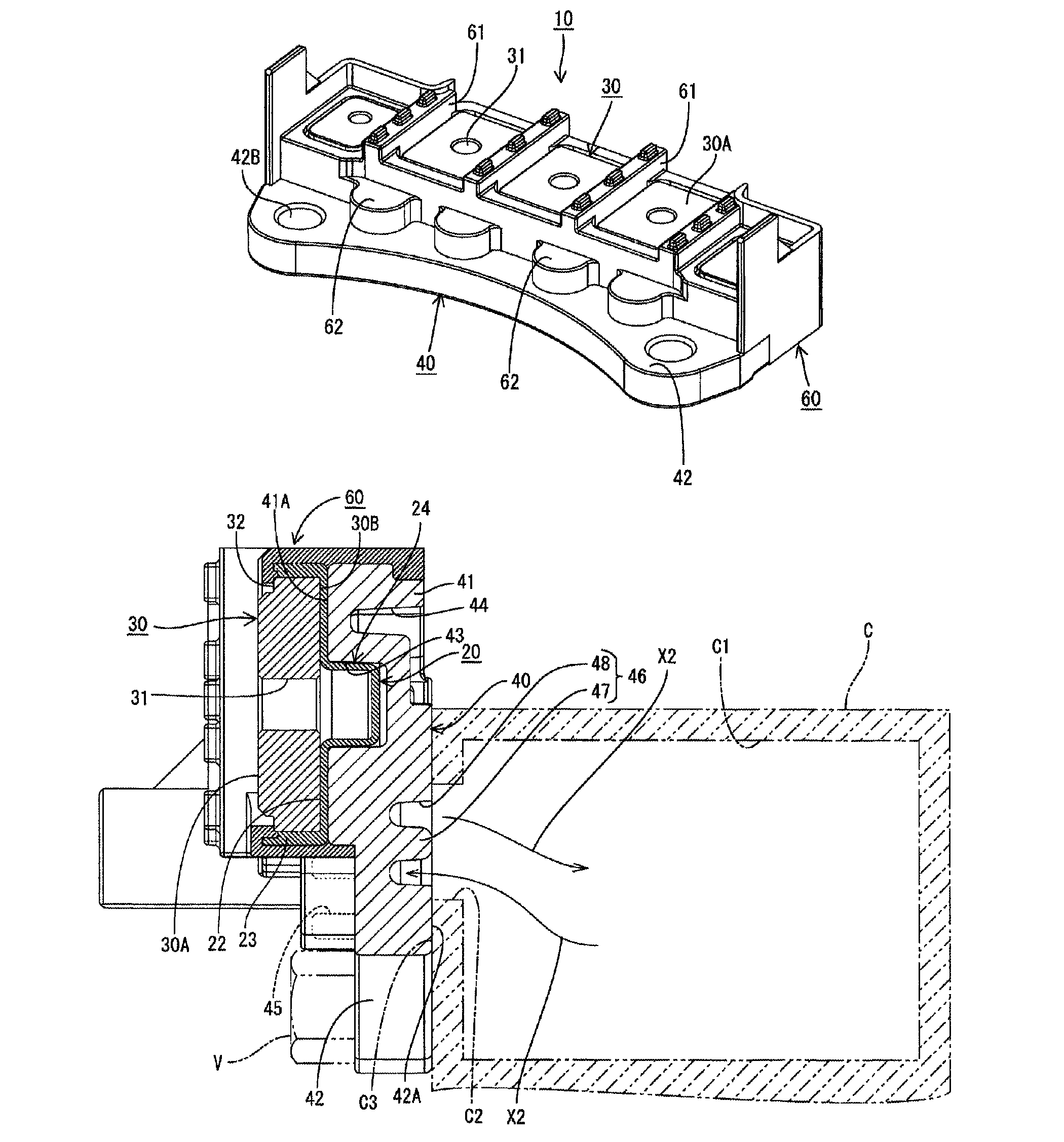
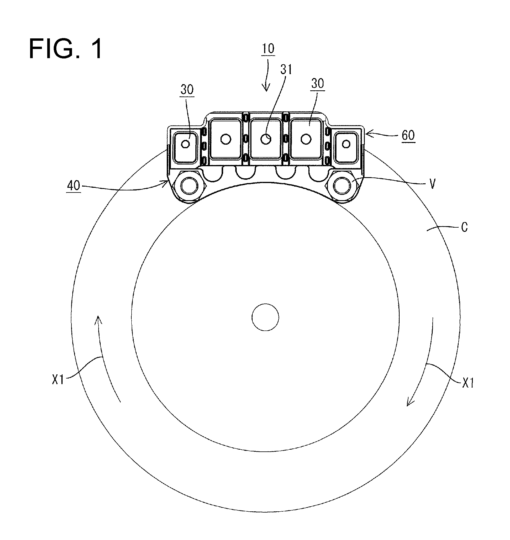
[0028]A terminal block in accordance with the invention is identified by the numeral 10 in the figures and is to be mounted on a substantially cylindrical motor case C that houses a three-phase alternating current motor installed in a vehicle, such as an electric vehicle or a hybrid vehicle, as shown in FIG. 1. A coolant flow path C1 is provided in an outer periphery of the motor case C and accommodates a flow of coolant, such as water or other cooling fluid for cooling the unillustrated motor body. The coolant flow path C1 is provided circularly to cover the outer peripheral surface of the motor body over the entire circumference, and the coolant is circulated in a circumferential direction X1 about a center axis of the motor body.

[0029]The terminal block 10 electrically connects a three-pole busbar in the unillustrated three-phase alternating current motor and a three-pole busbar in an unillustrated inverter.

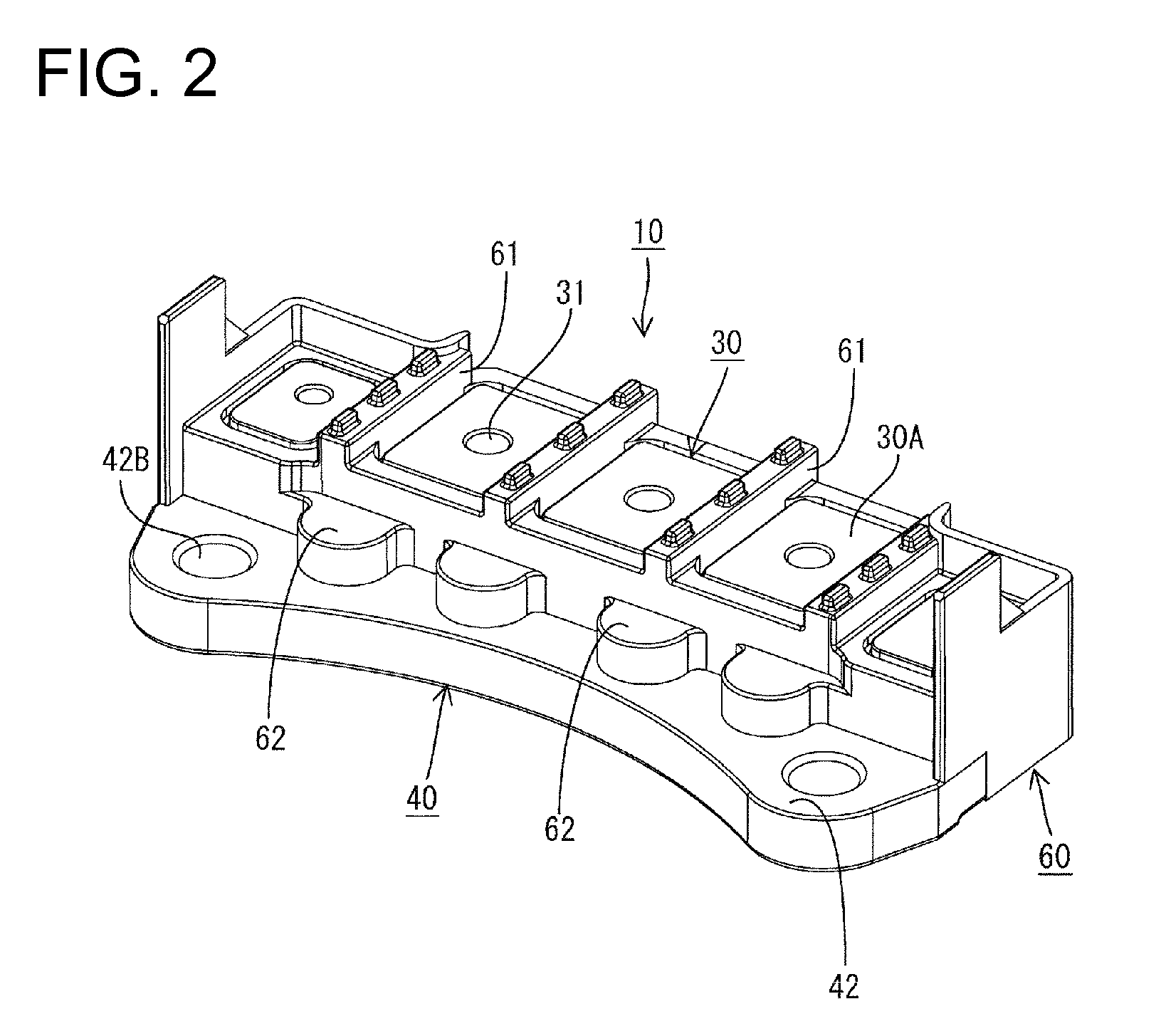
[0030]As shown in FIG. 7, the terminal block 10 includes nuts 30 on which...


PUM


Abstract

A terminal block (10) to be fixed to a motor case (C) which houses a motor body and includes a coolant flow path (C1) and adapted to fasten busbars by tightening bolts includes nuts (30) for tightening the bolts, and a heat sink (40) made of aluminum die-cast and held in close contact with the nuts (30) via an insulation plate (20) behind the nuts (30). The heat sink (40) includes a heat radiating portion (46) which comes into contact with cooling water passing in the coolant flow path (C1) of the motor case (C).

Description

BACKGROUND OF THE INVENTION[0001]1. Field of the Invention[0002]The invention relates to a terminal block and to a motor provided therewith.[0003]2. Description of the Related Art[0004]Japanese Unexamined Patent Publication No. 2008-98007 discloses a terminal block for electrically connecting conductive members, such as busbars, extending from electric devices, such as a motor and an inverter. This terminal block electrically connects the conductive members of respective electric devices by placing the conductive members one over another on metal nuts insert molded into a terminal block body. Bolts then are screwed into the nuts to fasten the conductive members to the metal nuts.[0005]The electric devices generally generate a large amount of heat and the heat is transferred from the electric devices to the conductive members. As a result, the terminal block connected to the conductive members becomes hot. Further, a large current flow also causes the conductive members to generate h...

Claims


Application Information

Patent Timeline
Patent Type & Authority Patents(United States)
IPC IPC(8): H02K11/00H02K9/19H02K5/22H01R9/22H01R9/24F28D15/00H02K9/00H01R4/30
CPCH01R9/22H02K5/225H02K9/19H02K5/20H01R4/302H01R2201/10H02K5/203
Inventor AKUTA, DAISUKE
Owner SUMITOMO WIRING SYST LTD
Why Eureka
Try Eureka