Heat storage member

Active Publication Date: 2017-10-05
NGK INSULATORS LTD +1
View PDF0 Cites 2 Cited by
  • Summary
  • Abstract
  • Description
  • Claims
  • Application Information

AI Technical Summary

Benefits of technology

[0010]As mentioned above, chemical heat storage has such an advantage that heat can be stored at relatively high density for a long time and can be reused. However, a chemical heat storage device using a chemical heat storage material has a problem, that is, low responsiveness of heat generation and h

Problems solved by technology

However, a chemical heat storage device using a chemical heat storage material has a problem, that is, low responsiveness of heat generation and heat absorption.
However, it is difficult for the conventional chemical heat storage device to generate the heat promptly.
The reason for the difficulty in generating the heat promptly is low thermal conductivity of the chemical heat storage material.
However, due to the low thermal conductivity of the chemical heat storage material, it takes time to radiate the generated heat.
Furthermore, the generated heat is transferred to the chemical heat storage material in a non-reacting part, which deteriorates reactivity (reactivity of the exothermic

Method used


Image

  • Heat storage member
  • Heat storage member
  • Heat storage member

Examples


example 1

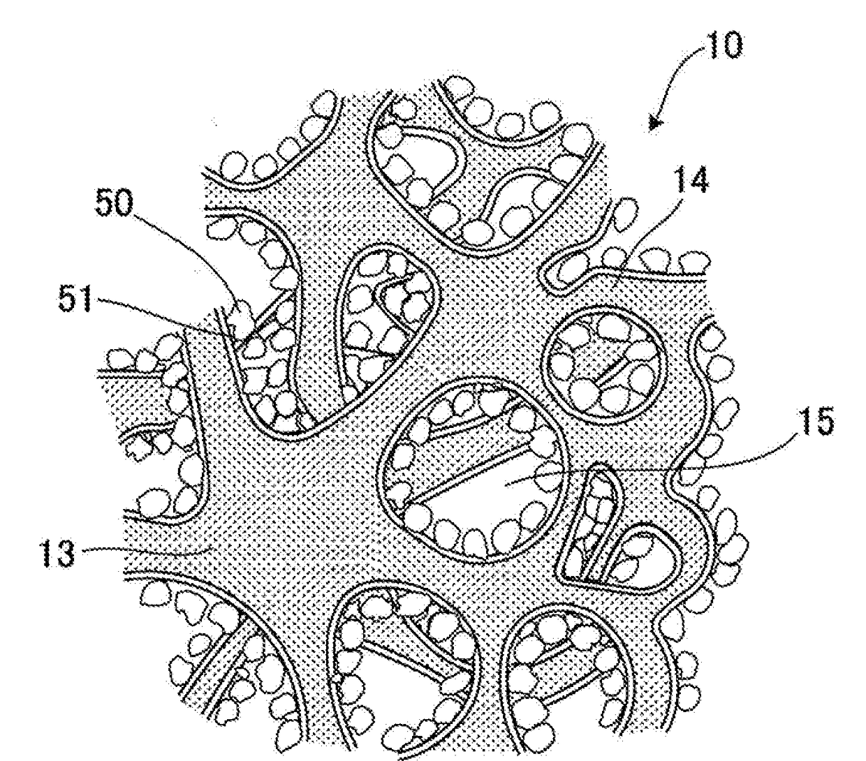
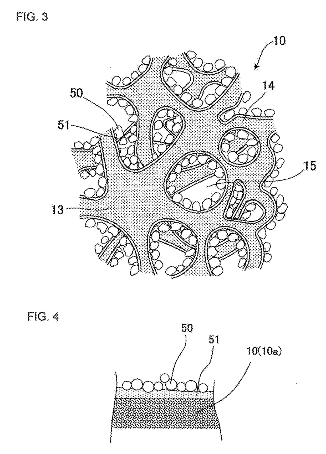
[0118]First, SiC powder of 99.7 parts by mass and metal Si powder of 0.3 parts by mass were mixed to obtain a mixed powder. A binder, a pore former, and water were added to this mixed powder so as to prepare a kneaded material for molding. As the SiC powder, the powder having an average particle diameter of 100 μm was applied. As the Si powder, the powder having an average particle diameter of 10 μm was applied.

[0119]Next, the prepared kneaded material for molding was formed by extrusion so as to obtain a Si—SiC formed body including a void.

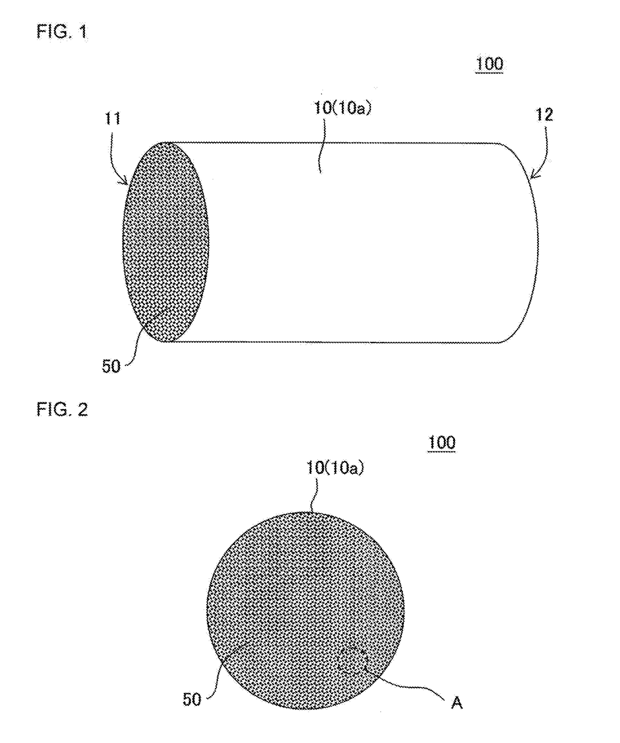
[0120]Next, the obtained Si—SiC formed body was fired at a temperature of 1440° C. for 5 hours so as to produce a porous Si—SiC substrate including the void. The obtained substrate had a round pillar shape having an axial length of 100 mm and including a first end face and a second end face each having a radius of 50 mm.

[0121]With regard to the obtained substrate, a “content ratio of SiC and content ratio of Si in the substrate” was measured by t...

examples 2 to 10

[0134]Each heat storage member was produced in the same manner as in Example 1 except that a coating layer was formed by changing composition of raw material powder for the coating layer. Composition and a softening point of each coating layer in Examples 2 to 10 were found to be those shown in Table 2. Evaluation results regarding the produced heat storage member are shown in Table 1.

examples 11 to 14

[0135]Each heat storage member was produced in the same manner as in Example 1 except that a coating layer was formed so as to include protrusions having a difference between recesses and protrusions of 0.5 to 100 μm. Each coating layer in Examples 11 to 14 was a layer including at least one of SiC particles, metal Si particles, Si—SiC particles, and C particles in the glass coating layer. Those heat storage members including particulates in their coating layer such as the heat storage members in Examples 11 to 14 are shown as “presence” in a column of “presence or absence of particulates” in Table 3. On the other hand, those heat storage members including no particulates in their coating layer such as the heat storage member in Example 1 are shown as “absence” in a column of “presence or absence of particulates” in Table 1. An average particle diameter of the particulates dispersed in the coating layer was measured by observing compositional images by using an energy dispersive X-r...


PUM


Abstract

A heat storage member including: a substrate containing a SiC sintered body as a principal ingredient; a coating layer disposed at least to a part of surface of the substrate; and a heat storage material disposed at least to a part of a surface of the coating layer and configured to store and radiate heat by a reversible chemical reaction with a reaction medium or a heat storage material configured to store and radiate heat by physical adsorption to a reaction medium and by physical desorption from a reaction medium. A softening point of the coating layer is a temperature at 1000° C. or less.

Description

[0001]The present application is an application based on JP-2016-73486 filed on Mar. 31, 2016 with Japan Patent Office, the entire contents of which are incorporated herein by reference.BACKGROUND OF THE INVENTIONField of the Invention[0002]The present invention relates to a heat storage member. More specifically, the present invention relates to a heat storage member having excellent durability and capable of achieving highly-responsive heat radiation and heat absorption by a chemical reaction or physical adsorption and physical desorption between a heat storage material and a reaction medium.Description of the Related Art[0003]In the related art, the following technique has been proposed. That is, exhaust heat from an automobile and the like is recovered and stored by using a heat storage material, and the recovered and stored heat is utilized to activate a catalyst (a catalyst for disposing exhaust gas) when starting an engine (see Patent Documents 1 to 3). According to such a te...

Claims


Application Information

Patent Timeline
IPC IPC(8): F28D20/00
CPCF28D20/003C09K5/16Y02E60/14
Inventor MIWA, SHINICHIKINOSHITA, TOSHIHARUHIMOTO, IORI
Owner NGK INSULATORS LTD
Why Eureka
Try Eureka