Tangent angle circuit in an LCD driving system and LCD driving system

a technology of tangent angle circuit and driving system, which is applied in the direction of electric digital data processing, instruments, computing, etc., can solve the problems of not providing an optimal effect of reducing feedback voltage and regulating linear variation effect, so as to reduce the burden of load discharged charges on the discharging modules, reduce the temperature, and avoid the congestion of components and occupies space on the control board

Inactive Publication Date: 2013-03-21
TCL CHINA STAR OPTOELECTRONICS TECH CO LTD
View PDF13 Cites 12 Cited by
  • Summary
  • Abstract
  • Description
  • Claims
  • Application Information

AI Technical Summary

Benefits of technology

[0051]In the present invention, according to parasitic capacitance of each of the scan line driving circuits, resistance of a variable resistor externally connected to a discharge resistor is adjusted so as to regulate a discharge slope of the corresponding scan line driving circuit; thereby, the tangent angle circuit is suitable for use with scan line driving circuits having different parasitic capacitance values. Moreover, by distributing the discharging modules on each of the scan line driving circuits respectively, the burden of load discharged charges on the discharging modules is reduced to avoid occurrence of an overhigh temperature; and because the discharging modules are spatially separated, congestion of components and occupation of space on the control board are avoided, which is further favorable for reducing the temperature, releasing the space of the control board and reducing the area of the control board.

Problems solved by technology

Unfortunately, the prior art tangent angle circuits cannot meet the needs for different parasitic capacitance values, so they cannot provide an optimal effect of reducing the feedback voltage and regulating the linear variation effect.

Method used


Image

  • Tangent angle circuit in an LCD driving system and LCD driving system
  • Tangent angle circuit in an LCD driving system and LCD driving system
  • Tangent angle circuit in an LCD driving system and LCD driving system

Examples


Embodiment Construction

[0063]It shall be understood that, the embodiments described herein are only intended to illustrate but not to limit the present invention.

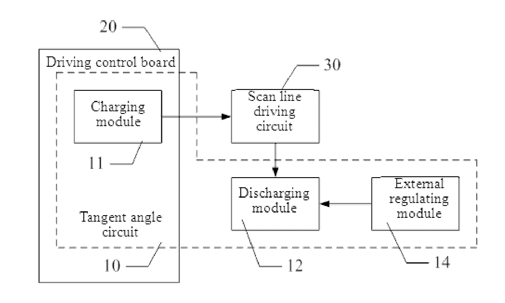
[0064]As shown in FIG. 1, a tangent angle circuit 10 in a liquid crystal display (LCD) driving system according to an embodiment of the present invention is connected to a plurality of scan line driving circuits 30 and comprises:

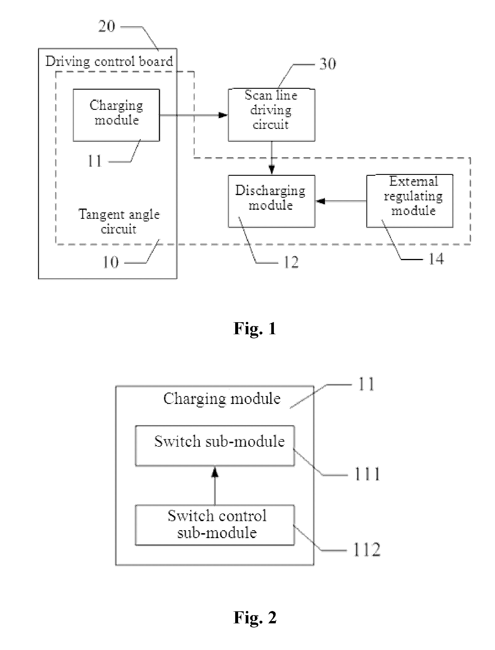
[0065]a charging module 11, being integrated on a control board 20 and configured to receive input of a direct current (DC) driving voltage and output a cut-in voltage to charge the scan line driving circuits 30;

[0066]a plurality of discharging modules 12, being integrated on the scan line driving circuits 30 respectively and configured to control the corresponding scan line driving circuits 30 to discharge; and

[0067]a plurality of external regulating modules 14, being externally connected to the scan line driving circuits 30 respectively and connected to the corresponding discharging modules 12 to regulate the dischargin...


PUM


Abstract

A tangent angle circuit in a liquid crystal display (LCD) driving system comprises: a charging module integrated on a control board for receiving input of a direct current (DC) driving voltage and outputting a cut-in voltage to charge a plurality of scan line driving circuits; a plurality of discharging modules integrated on the scan line driving circuits respectively for controlling the corresponding scan line driving circuits to discharge; and a plurality of external regulating modules externally connected to the scan line driving circuits respectively and connected to the corresponding discharging modules to regulate the discharging modules so as to control a discharging rate of the scan line driving circuits. In the present invention, a discharge slope of the corresponding scan line driving circuit can be regulated; thereby, the tangent angle circuit is suitable for use with scan line driving circuits having different parasitic capacitors.

Description

BACKGROUND[0001]1. Technical Field[0002]The present invention relates to the field of liquid crystal display (LCD) driving, and more particularly, to a tangent angle circuit in an LCD driving system and the LCD driving system.[0003]2. Description of Related Art[0004]In the LCD driving system architecture, in order to reduce a feedback voltage and the linear variation effect, an LCD driving system must be provided with a tangent angle circuit for regulating a slope of a driving voltage waveform (i.e., for generating a tangent angle). Currently, the tangent angle circuit has been widely applied in all kinds of LCD driving systems. Usually, the tangent angle circuit has all of its components installed on a control board of the LCD driving system, and adopts a metal-oxide-semiconductor (MOS) transistor as a switch component to control a cut-in voltage to charge scan line driving circuits. Meanwhile, discharging modules are connected in parallel to a discharge voltage output of the scan ...

Claims


Application Information

Patent Timeline
Patent Type & Authority Applications(United States)
IPC IPC(8): G09G5/00G09G3/36
CPCG09G5/00G09G2330/045G09G3/3696G09G3/3677
Inventor LIN, PO-SHENTAN, XIAOPINGCHEN, MING-WEI
Owner TCL CHINA STAR OPTOELECTRONICS TECH CO LTD
Why Eureka
Try Eureka