
Integrated circuit with on-die distributed programmable passive variable resistance fuse array and method of making same

a technology of programmable passive variable resistance and integrated circuit, which is applied in the field of integrated circuits, can solve the problems of affecting yield, affecting cost and complexity of dies, and fairly complex sensing logic to reliably read the differences between unprogrammed and programmed fuse arrays

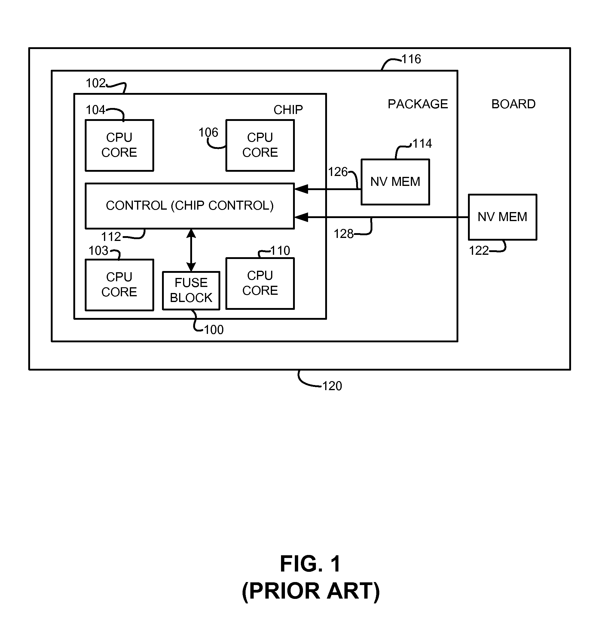
Inactive Publication Date: 2013-03-21
ADVANCED MICRO DEVICES INC
View PDF4 Cites 72 Cited by
  • Summary
  • Abstract
  • Description
  • Claims
  • Application Information

AI Technical Summary

Benefits of technology

The patent text describes an improved configuration structure for integrated circuits that overcomes the drawbacks of current methods that use on-die fuses and off-chip or off-package memories. The invention provides a more efficient and cost-effective way to provide configuration information for integrated circuits. The technical effect of the invention is to provide a more efficient and cost-effective way to provide configuration information for integrated circuits.

Problems solved by technology

The sensing logic can be fairly complex to reliably read the differences between an unprogrammed and a programmed fuse.
Such fuses also take up large areas of an integrated circuit which can impact the cost and the complexity of the dies and can impact yield and hence are typically a limited resource.
In addition, the fuses are typically not very close to the functional block for which they are used thereby also limiting the location of the fuses and wiring adjacent to the corresponding functional block.

Method used


Image

  • Integrated circuit with on-die distributed programmable passive variable resistance fuse array and method of making same
  • Integrated circuit with on-die distributed programmable passive variable resistance fuse array and method of making same
  • Integrated circuit with on-die distributed programmable passive variable resistance fuse array and method of making same

Examples


Embodiment Construction

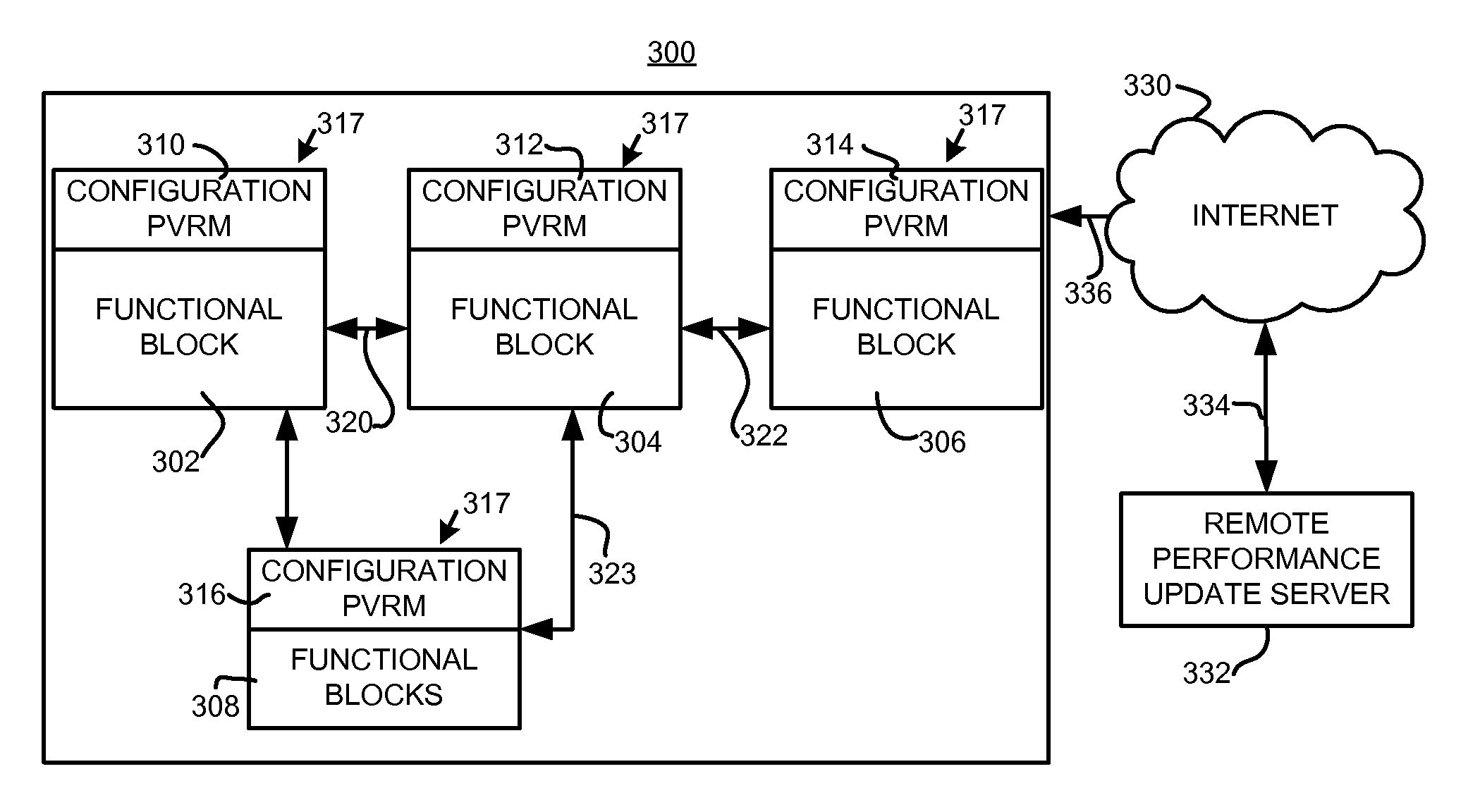
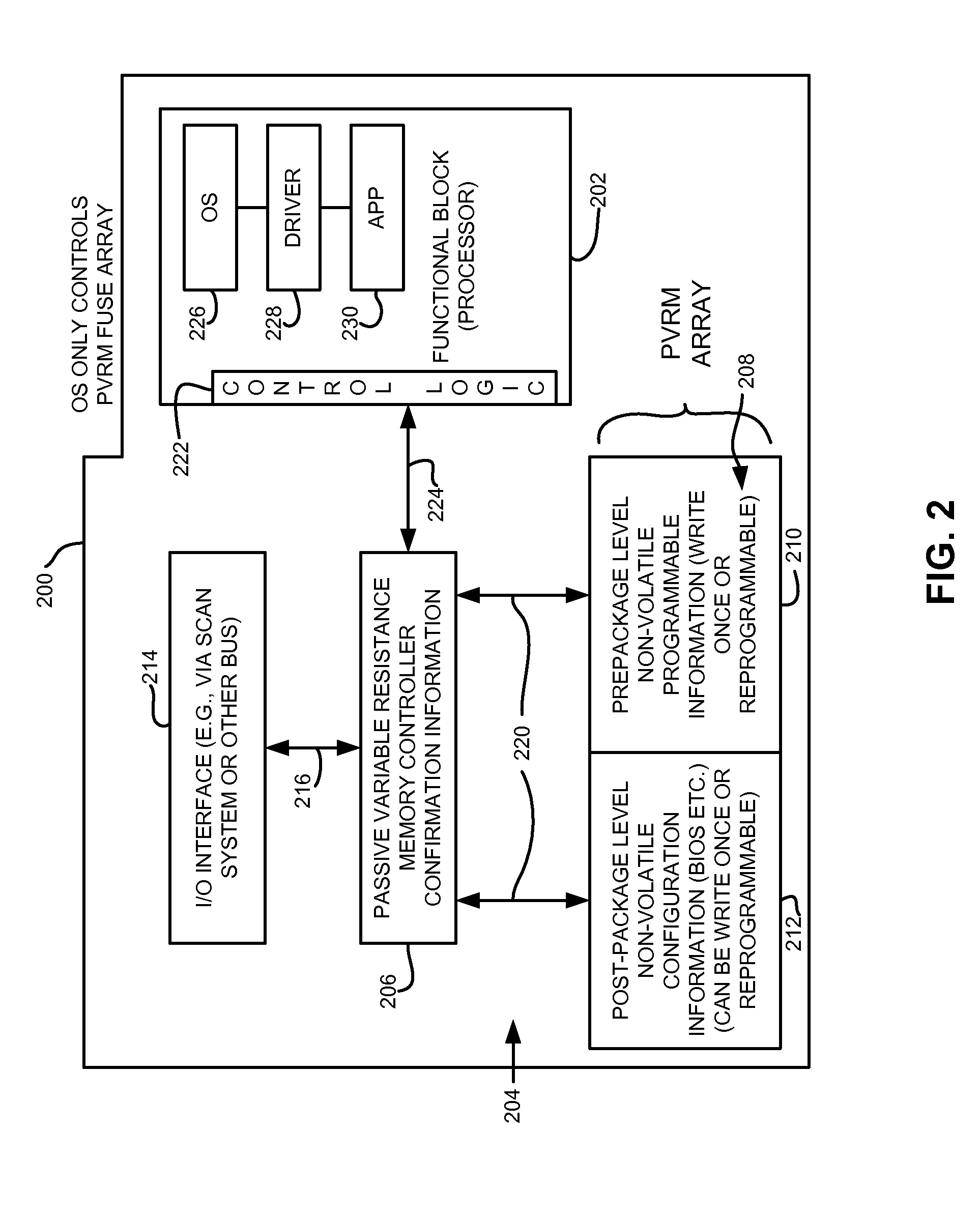
[0015]Briefly, an integrated circuit employs a plurality of functional blocks, such as but not limited to, processors (e.g., cores), and an on-die distributed programmable passive variable resistance memory array configured to provide configuration information for each of the plurality of functional blocks. A corresponding sub-portion of the on-die distributed programmable passive variable resistance memory array is fabricated in layers above each respective plurality of functional blocks. The on-die distributed programmable passive variable resistance memory array is used as either non-volatile prepackage configuration information store, or a non-volatile post-package configuration information store that may allow dynamic changing of hardware configuration of the functional blocks both during normal operation and non-normal operation (e.g., prior to die packaging). Employing a distributed programmable passive variable resistance memory array wherein sub-portions are located in laye...


PUM


Abstract

An integrated circuit employs a plurality of functional blocks, such as but not limited to, processors (e.g., cores), and an on-die distributed programmable passive variable resistance memory array configured to provide configuration information for each of the plurality of functional blocks. A corresponding sub-portion of the on-die distributed programmable passive variable resistance memory array is fabricated in layers above each respective plurality of functional blocks. The on-die distributed programmable passive variable resistance memory array is used as either non-volatile prepackage configuration information store, or a non-volatile post-package configuration information store that may allow dynamic changing of hardware configuration of the functional blocks both during normal operation and prior to die packaging. A method for making the same is also disclosed.

Description

RELATED APPLICATIONS[0001]This application claims priority to Provisional Application Ser. No. 61 / 535,728, filed on Sep. 16, 2011, having inventors Don R. Weiss et al., titled “AN INTEGRATED CIRCUIT WITH ON-DIE DISTRIBUTED PROGRAMMABLE PASSIVE VARIABLE RESISTANCE FUSE ARRAY AND METHOD OF MAKING SAME”, and is incorporated herein by reference.BACKGROUND OF THE INVENTION[0002]The disclosure relates generally to integrated circuits that employ integrated fuses and more particularly to integrated circuits that employ non-volatile memory used to provide hardware configuration information.[0003]Integrated circuits are known to employ on-die electrically programmed fuses that are write once fuses that may require silicon or metal that is burned to an open circuit by applying a high programming voltage, typically higher than the nominal operating voltage of the integrated circuit. Programming transistors are used to select the fuse and burn the fuse open in an open circuit thereby fixedly se...

Claims


Application Information

Patent Timeline
IPC IPC(8): H01L45/00G11C11/00H01L21/02
CPCH01L27/11286H01L27/0207H01L27/101H01L27/222H01L27/24H01L45/06H01L45/08H01L45/141H01L45/146H01L45/04H10B63/00H10B61/00H10N70/24H10N70/20H10N70/882H10N70/231H10N70/8833H10B20/60
Inventor WEISS, DONALD R.WUU, JOHN J.
Owner ADVANCED MICRO DEVICES INC
Learn More