Ethernet multicast method and device

Active Publication Date: 2013-03-21
HUAWEI TECH CO LTD
View PDF14 Cites 3 Cited by
  • Summary
  • Abstract
  • Description
  • Claims
  • Application Information

AI Technical Summary

Benefits of technology

[0026]In the embodiments of the present invention, when selecting the multicast root node, the multicast management device selects the switch satisfying a particular optimization condition such as a switch with a closest/closer distance to the host/multicast source, as the multicast root node. Compared with the conventional art

Problems solved by technology

However, since the scale of traditional Ethernet networks is restricted due to their poor expandability, the advantage of multicasting in the Ethernet networks cannot be exhibited.
However, when performing multicast in Ethernet networks with the SEATTLE architecture, the inventors select a multicast root node, randomly map a multicast group to

Method used


Image

  • Ethernet multicast method and device
  • Ethernet multicast method and device
  • Ethernet multicast method and device

Examples


embodiment 1

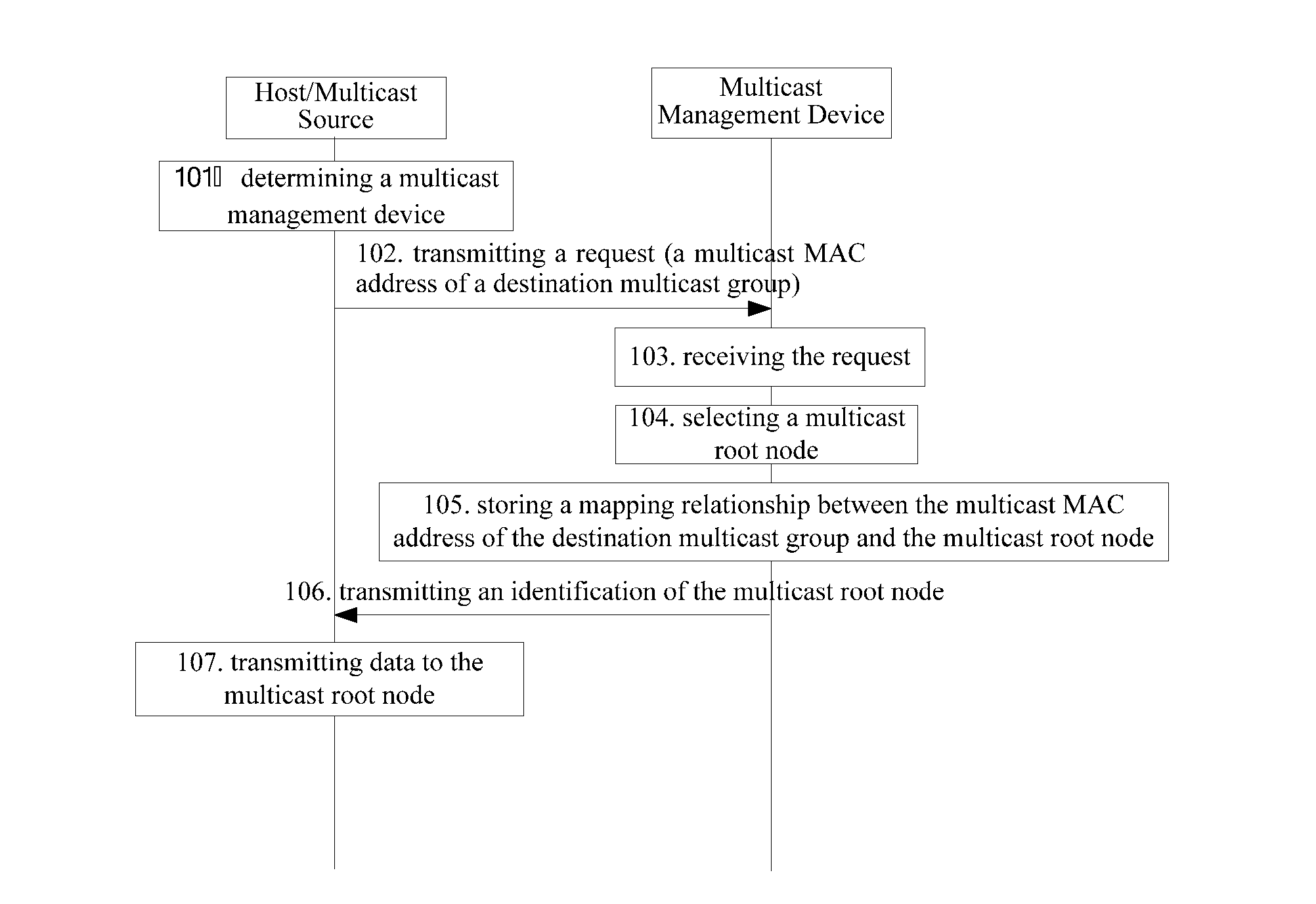
[0039]The embodiment of the present invention is applied in a scenario in which a layered network topology is supposed to be used, wherein all multicast management devices in the same Ethernet network logically constitute a DHT loop and they jointly manage multicast groups within the entire Ethernet. Each multicast management device under the loop manages a group of switches, and these switches and multicast management devices can be either directly connected through links, or interconnected through other devices such as switches. Of course, the practical application scenario is not limited to the layered network.

[0040]The embodiment of the present invention provides an Ethernet multicast method, comprising the following steps:[0041]1001. receiving a request from a host / multicast source, the request carrying a multicast MAC address of a destination multicast group;[0042]1002. selecting, according to the request, a switch satisfying a particular optimization condition as a multicast ...

embodiment 2

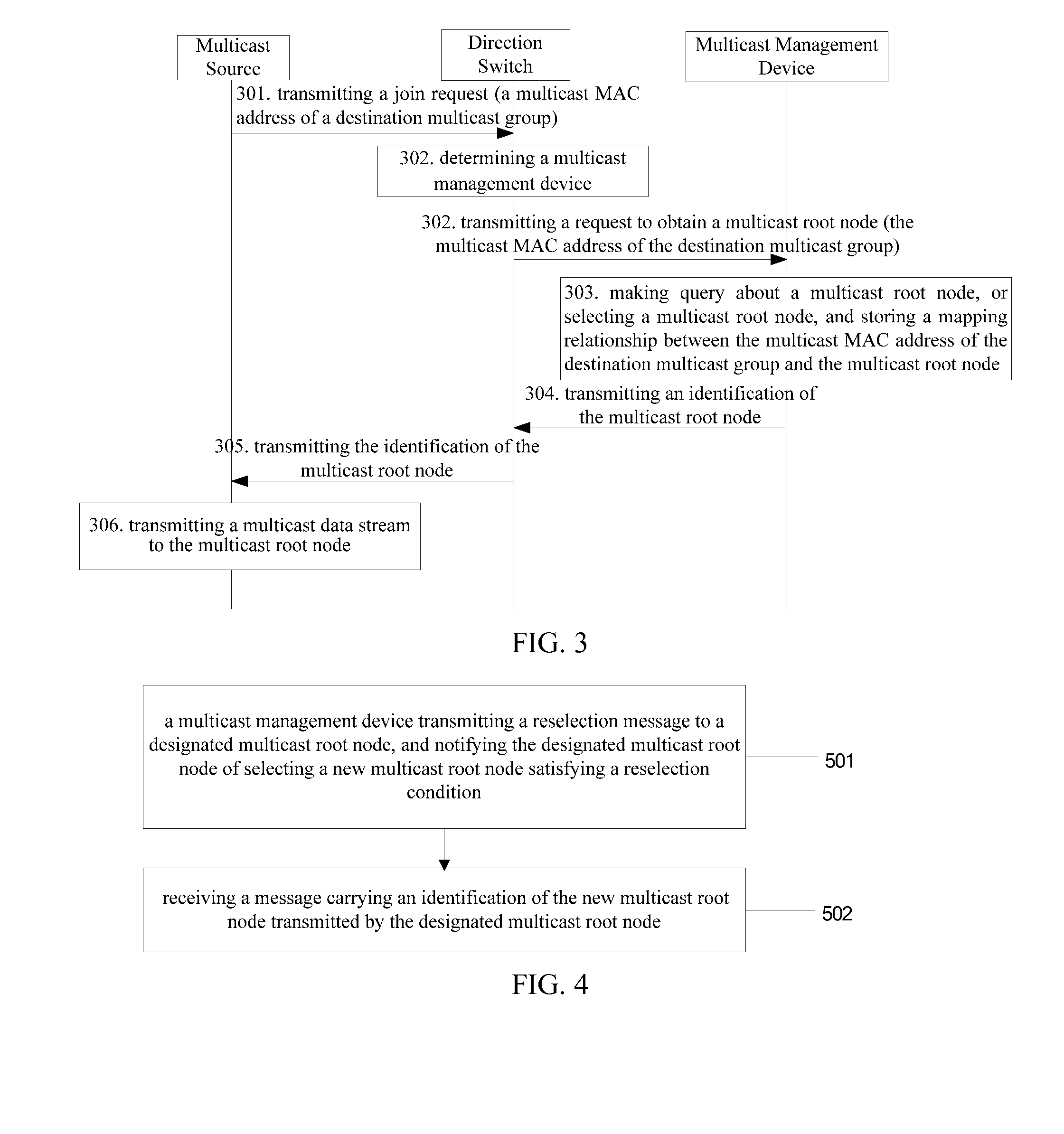
[0092]In order to perform better management of a multicast group within the Ethernet, the embodiment of the present invention further provides an optimized technical solution, that is, at a different time, in the embodiment of the present invention, the multicast management device may trigger reselection of a multicast root node and adjust the existing multicast tree, so that it is possible to construct a multicast distribution tree more reasonably, thereby further improving the capability of multicast data distribution within the Ethernet. A detailed description of reselection of the multicast root node is given below.

[0093]As shown in FIG. 4, there is provided an Ethernet multicast method, comprising the following steps:[0094]501. A multicast management device transmits a reselection message to a designated multicast root node, and notifies the designated multicast root node of selecting a new multicast root node satisfying a reselection condition. During specific application, the...

embodiment 3

[0111]The invention of the present invention provides a communication device, which as shown in FIG. 6 comprises: a determining unit 11, a transmission unit 12 and a reception unit 13.

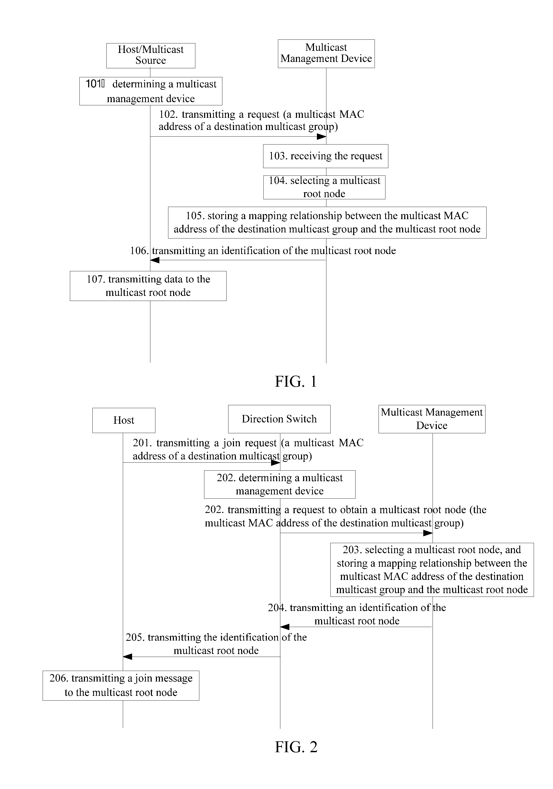
[0112]When the communication device intends to join a destination multicast group, the determining unit 11 is used to determine a multicast management device in accordance with a multicast MAC address of the destination multicast group; the transmission unit 12 is used to transmit, to the multicast management device, a request carrying the multicast MAC address of the destination multicast group. The multicast management device returns an identification of a corresponding multicast root node in accordance with the multicast MAC address of the destination multicast group, and the identification may specifically be an IP address, a MAC address or other identifying character such as an ID of the multicast root node.

[0113]The reception unit 13 is used to receive the identification of the multicast root nod...


PUM


Abstract

An Ethernet multicast method and device are provided, which relate to the communications technology field, and improve the capability of distributing multicast data in the Ethernet. The method includes: receiving a request from a host/multicast source, wherein the request carries a multicast Media Access Control (MAC) address of a destination multicast group; selecting, according to the request, a switch satisfying a particular optimization condition as a multicast root node corresponding to the multicast MAC address of the destination multicast group when it is determined that the multicast MAC address of the destination multicast group does not have the corresponding multicast root node; transmitting an identification of the multicast root node to the host/multicast source. The embodiments of the present invention are mainly applied to the process of the multicast data distribution in the Ethernet.

Description

CROSS-REFERENCE TO RELATED APPLICATIONS[0001]This application is a continuation of International Patent Application No. PCT / CN2011 / 073719, filed on May 6, 2011, which claims priority to Chinese Patent Application No. 201010226149.3, filed on Jul. 14, 2010, both of which are hereby incorporated by reference in their entireties.FIELD OF THE INVENTION[0002]The present invention relates generally to the communications technology field, and in particular to an Ethernet multicast method and device.BACKGROUND OF THE INVENTION[0003]With the vigorous development of the Ethernet technology, the performances of Ethernet switches are being constantly improved. Since the Ethernet switches are low-priced and maintained and configured at low cost, a lot of large-scaled networks such as Data Centers and Metropolitan Area Networks (MANs) adopt a large amount of Ethernet switches to perform networking. In the network constructed by the Ethernet switches, the distribution of data in a multicasting man...

Claims


Application Information

Patent Timeline
IPC IPC(8): H04L12/54H04L45/16
CPCH04L12/413H04L45/16H04L12/185H04L12/40013H04L12/56
Inventor CHEN, XUELIANGSHI, GUANGYUWEN, LIUFEI
Owner HUAWEI TECH CO LTD
Why Eureka
Try Eureka