Loudspeaker and diaphragm therefor

a technology which is applied in the field of diaphragms and loudspeakers, can solve the problems of insufficient breakup frequency of diaphragms with the geometries above, and adversely affect the sound of loudspeakers

Active Publication Date: 2013-03-21
GP ACCOUSTICS (UK) LIMITED
View PDF9 Cites 23 Cited by
  • Summary
  • Abstract
  • Description
  • Claims
  • Application Information

AI Technical Summary

Benefits of technology

[0008]This invention primarily relates to a method of stiffening a radiating loudspeaker diaphra...

Problems solved by technology

They therefore adversely affect the sound of the loudspeaker.
Factors such as build height, moving mass target,...

Method used


Image

  • Loudspeaker and diaphragm therefor
  • Loudspeaker and diaphragm therefor
  • Loudspeaker and diaphragm therefor

Examples


Embodiment Construction

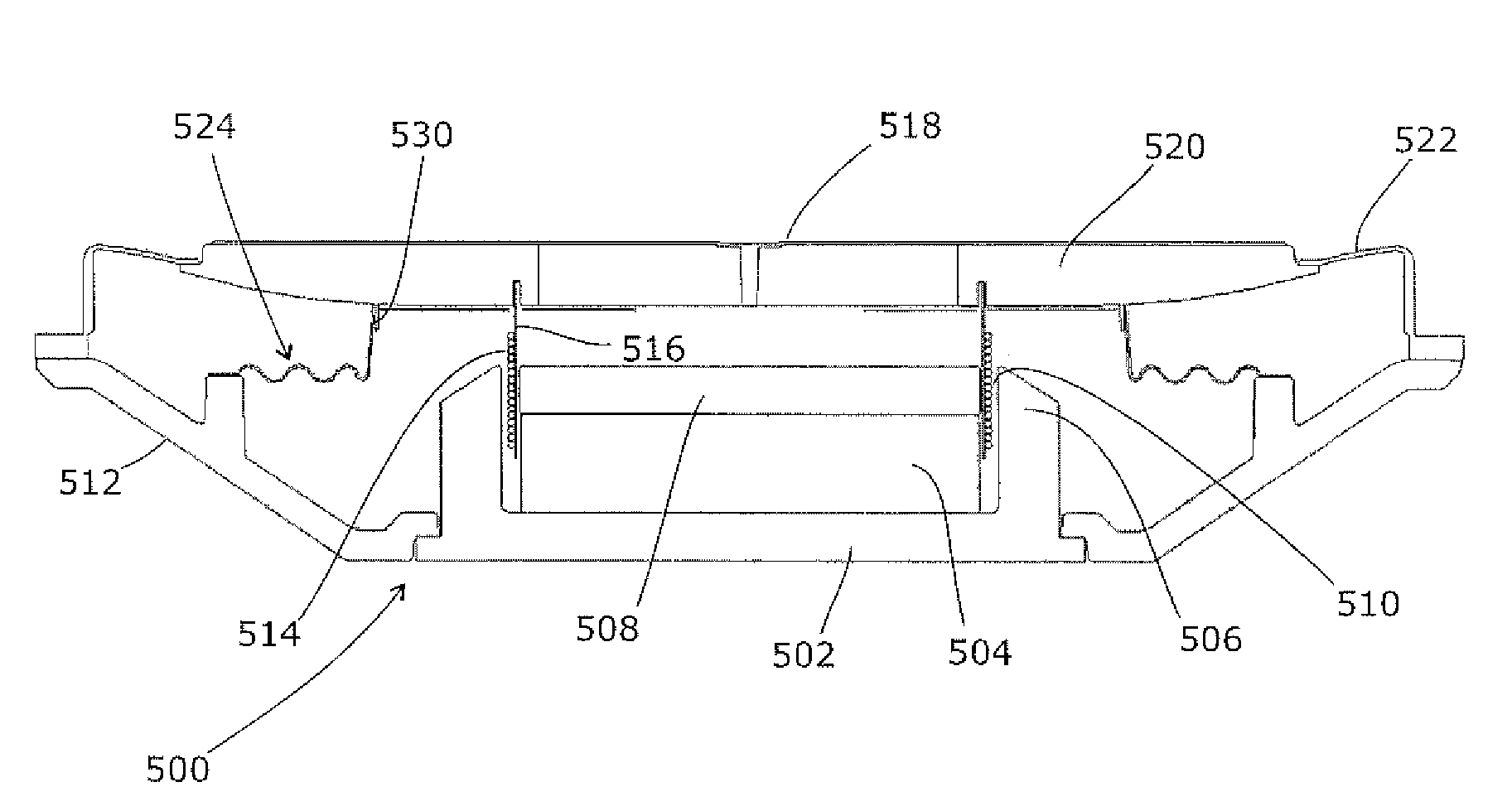
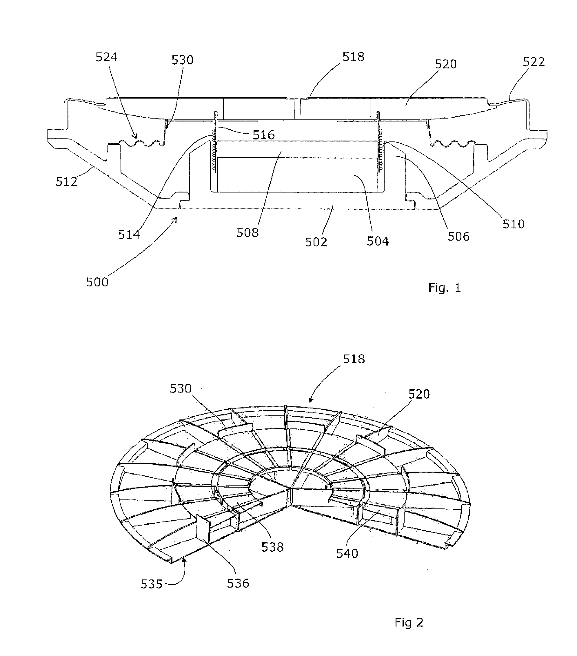
[0029]FIG. 1 shows a loudspeaker driver 500. A magnet assembly 502 carries a permanent magnet 504 and a central pole piece 508, and has a cylindrical outer pole piece 506 to define a magnetic field gap 510. A chassis 512 sits concentrically around the magnet assembly 502 and provides support for the other parts of the driver 500.

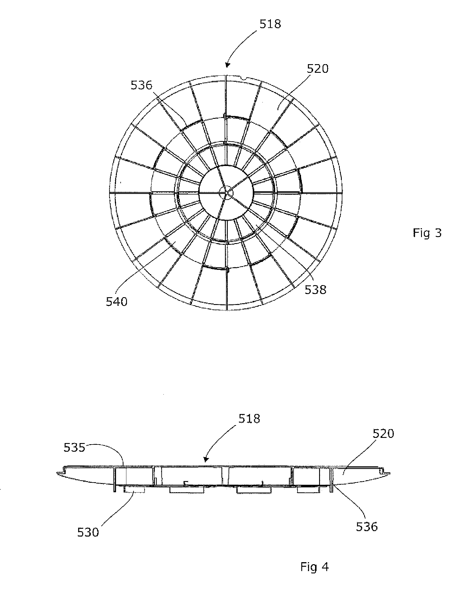
[0030]These include a voice coil 514 that is supported on a voice coil former 516 so as to lie at least partly within the magnetic field gap 510. The voice coil former 516 drives a diaphragm 518, which has a planar front surface in order to reduce the overall depth of the driver 500 as compared to a driver comprising a cone-shaped diaphragm. To provide a degree of rigidity, the diaphragm has stiffening ribs 520 on its rear face, and the voice coil former 516 is attached to these.

[0031]At its radially outermost extent, the diaphragm 518 is supported by a surround 522 which helps to centre the diaphragm 518 relative to the magnetic field gap 510, acts as an ai...


PUM


Abstract

A loudspeaker radiating diaphragm can be stiffened to help increase the breakup frequency to above the working frequency range of the driver concerned, by forming it of a moulded part and an attached formed part. The moulded part is a radiating surface with stiffening ribs. The formed part is a thin surface of high modulus material, attached to the rear of the ribs. The overall structure can have significantly higher stiffness than either of the two parts. This helps in designing a loudspeaker driver that does not breakup within its working frequency range.

Description

[0001]This Application is a Section 371 National Stage Application of International Application No. PCT / GB2011 / 000642, filed Apr. 26, 2011 and published as WO / 2011 / 135291 A1, in English, which claims priority of GB Application No. 1007350.0, filed Apr. 30, 2010 the contents of which are hereby incorporated by reference in their entirety.FIELD OF THE INVENTION[0002]The present invention relates to the field of loudspeakers, and particularly relates to diaphragms and loudspeakers comprising them.BACKGROUND ART[0003]The radiating diaphragm of a loudspeaker typically vibrates axially, with one side thereby creating pressure waves outside the loudspeaker enclosure. At certain frequencies, there are natural structural resonances in the diaphragm and other moving parts. When the diaphragm is driven by the voice coil, these resonances may be excited. They correspond to peak displacements of the diaphragm, but other than the main resonance (at which the diaphragm may move pistonically) the d...

Claims


Application Information

Patent Timeline
IPC IPC(8): G10K13/00H04R1/00
CPCB26B21/225B26B21/52H04R1/00B26B21/528G10K13/00B26B21/521H04R7/02H04R7/10H04R7/125H04R7/14H04R7/08H04R7/122H04R31/003
Inventor DODD, MARK ALEXANDEROCLEE-BROWN, JACK ANTHONYDAVIDSON, JULIA
Owner GP ACCOUSTICS (UK) LIMITED
Why Eureka
Try Eureka