Diesel engine for automobile, control device and control method

a technology for automobiles and diesel engines, applied in the direction of electrical control, process and machine control, etc., can solve the problems of loss of nvh performance and increase of combustion noise, and achieve the effect of slowing down the main combustion, reducing the heat release rate at that time, and shortening the ignition delay of the fuel injected

Active Publication Date: 2013-03-21
MAZDA MOTOR CORP
View PDF9 Cites 17 Cited by
  • Summary
  • Abstract
  • Description
  • Claims
  • Application Information

AI Technical Summary

Benefits of technology

[0015]a pre-injection of injecting fuel at a predetermined timing after the pilot injection, to suppress thereby ignition of the fuel injected by the pilot injection and shorten an ignition delay of the fuel injected by the main injection.
[0016]In the above configuration of the diesel engine for automobiles being an engine having a comparatively low compression ratio where the geometric compression ratio is 15 or less, there is performed a main injection of injecting fuel near a compression top dead center at a specific region of predetermined load within an operating region on a relatively low-speed side, at a time where the engine main body is warm, and there are performed two fuel injections, namely a pilot injection and a pre-injection, at predetermined timings in the compression stroke prior to the main injection. As a result, there is shortened a pre-combustion period immediately before the main combustion, the heat release rate at that period is made comparatively higher, and it becomes also possible slow down the main combustion through shortening of the ignition delay by the main injection. As a result, combustion noise is reduced, and NVH performance is accordingly improved.

Problems solved by technology

This is likely to give rise to an increase in combustion noise and loss of NVH performance, all of which is problematic.

Method used


Image

  • Diesel engine for automobile, control device and control method
  • Diesel engine for automobile, control device and control method
  • Diesel engine for automobile, control device and control method

Examples


Embodiment Construction

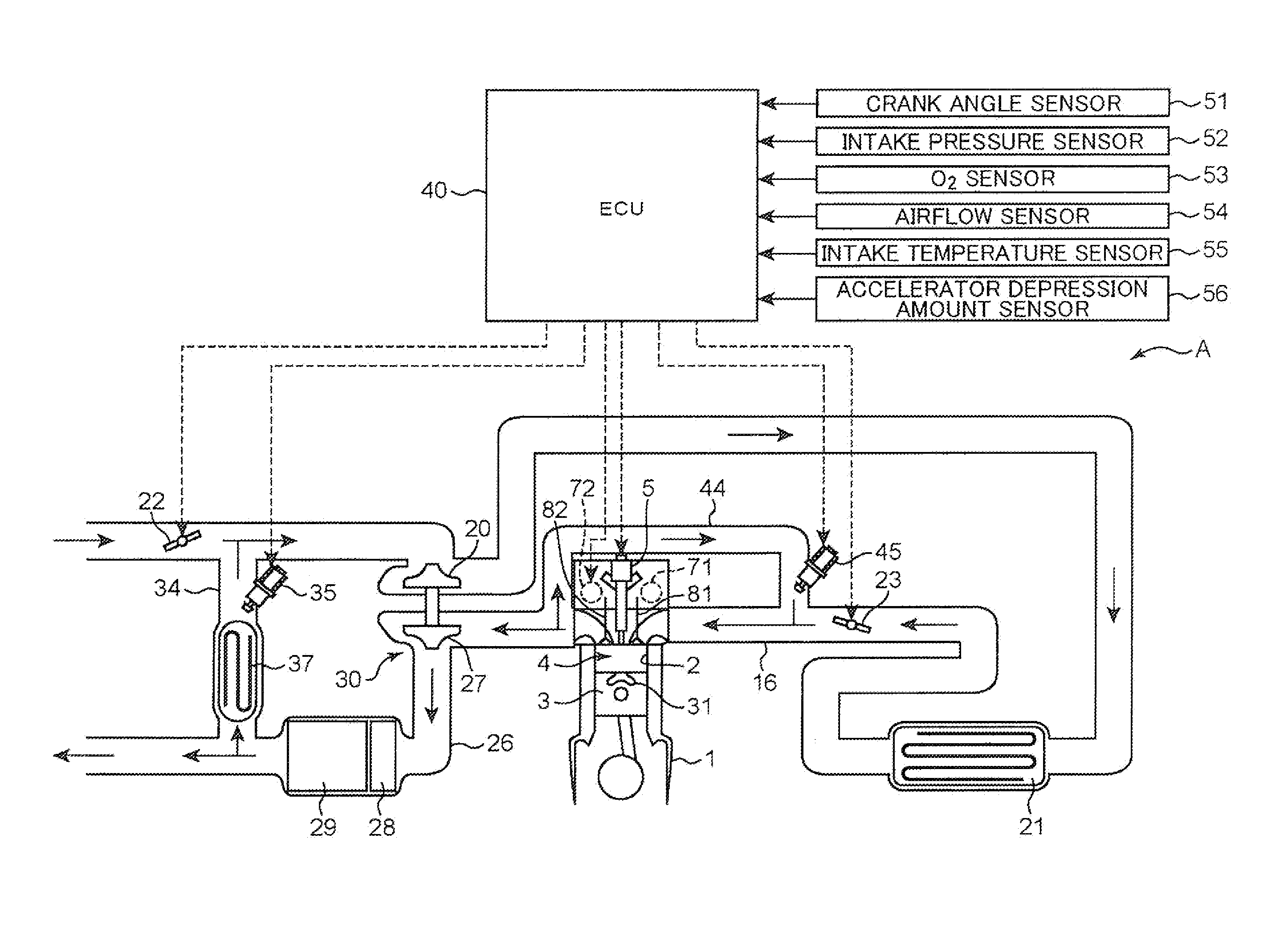
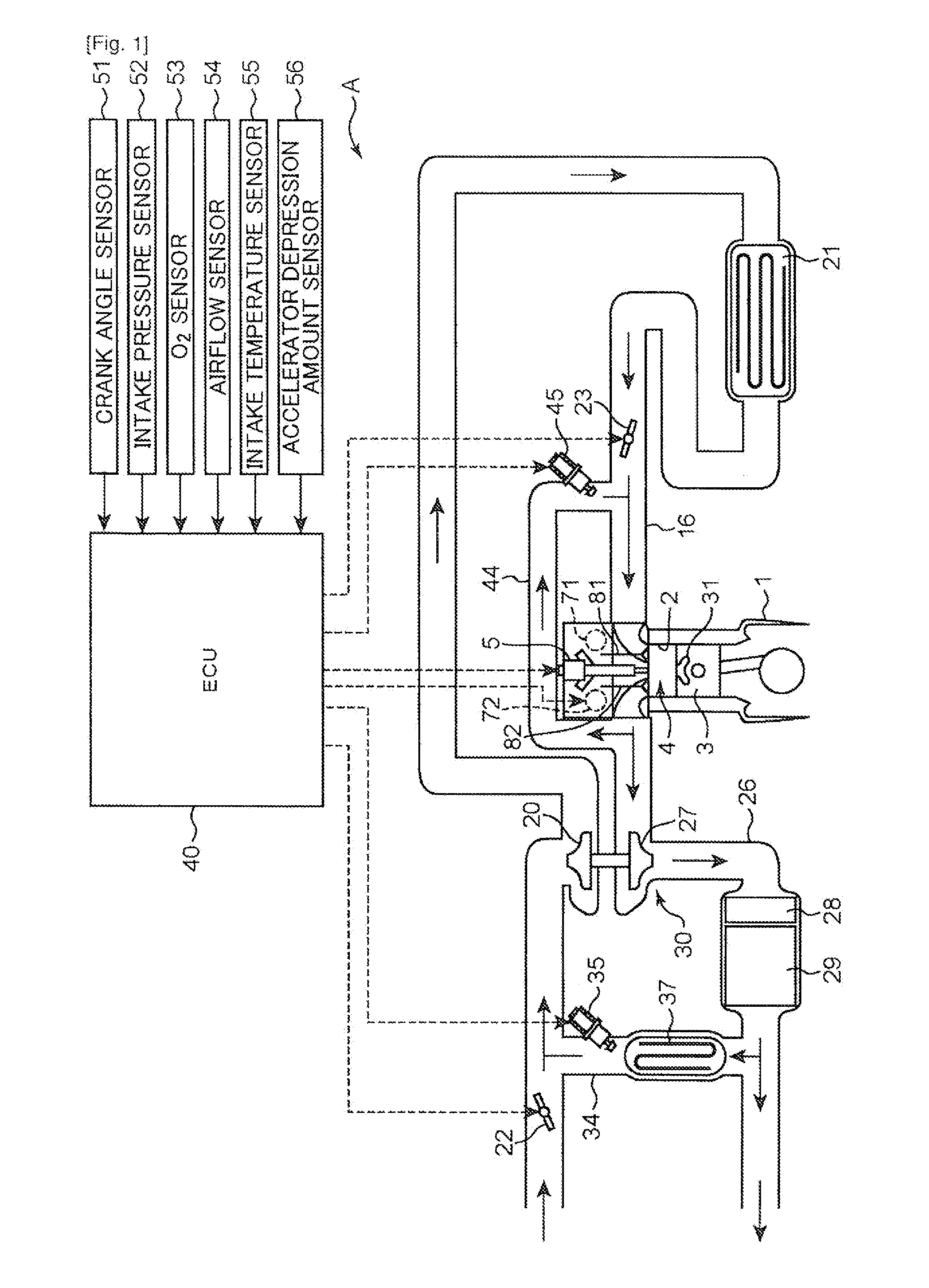
[0024]A diesel engine according to an embodiment is explained below with reference to accompanying drawings. Essentially, the preferred embodiments described below are merely illustrative in nature. FIG. 1 illustrates an example of an engine A, wherein the reference numeral 1 denotes an engine main body installed in a vehicle. The engine main body 1 is a diesel engine to which fuel having diesel oil as a main component is supplied, and has a plurality of cylinders 2, 2, . . . (only one cylinder is illustrated in the figure). A piston 3 is reciprocatingly insertion-fitted in each cylinder 2. On the top face of this piston 3 there is formed a cavity 31 that demarcates a reentrant-type combustion chamber 4.

[0025]On the ceiling portion of the combustion chamber 4 there is disposed an injector 5 (fuel injection valve), such that high-pressure fuel is directly injected into the combustion chamber 4 from an injection nozzle at the leading end portion of the injector 5. The engine main body...


PUM


Abstract

A geometric compression ratio in an engine main body 1 is set to 15 or less. Injection control means (ECU 40) performs a main injection of injecting fuel near a compression top dead center, and a preceding injection prior to the main injection at a specific region of predetermined load within an operating region on a relatively low-speed side. The injection control means performs, as the preceding injection, a pilot injection of performing injection at a timing such that at least part of a fuel spray reaches outside a cavity 31 on a top face of a piston, and a pre-injection of injecting fuel at a predetermined timing after the pilot injection, to suppress thereby ignition of the fuel injected by the pilot injection and shorten an ignition delay of the fuel injected by the main injection.

Description

TECHNICAL FIELD[0001]The present invention relates to a diesel engine for automobiles, and more particularly to a diesel engine having a comparatively low compression ratio where the geometric compression ratio is set to 15 or less.BACKGROUND ART[0002]In diesel engines installed in automobiles, a plurality of fuel injections are carried out in each cylinder during one engine cycle, with a view to, for instance, reducing the amount of NOx and soot in the exhaust gas, lowering noise and vibration, and improving fuel consumption and torque. For instance, Japanese Patent Application Publication No. 2009-293383 (hereafter, Patent document 1) discloses a fuel injection mode in which two injections, namely a pre-injection for premixing and a pre-injection for pre-heating, are performed ahead of a main injection for torque generation.[0003]Concerning the setting of injection timing in pre-injection for premixing and pre-injection for pre-heating, Patent document 1 also discloses the feature...

Claims


Application Information

Patent Timeline
Patent Type & Authority Applications(United States)
IPC IPC(8): F02D41/26
CPCF02B1/12F02D41/402F02D13/0207F02D13/0246F02D13/0273F02D41/04F02D41/403F02M25/0707F02M25/0709F02M25/0727F02M25/0752Y02T10/44Y02T10/123Y02T10/18F02D41/3035F02B2275/14F02M26/01F02M26/05F02M26/06F02M26/23Y02T10/12Y02T10/40
Inventor MORINAGA, SHINICHISHIMO, DAISUKEMARUYAMA, KEIJIMINAMOTO, HIROSHISHIRAHASHI, NAOTOSHIFUKUDA, DAISUKE
Owner MAZDA MOTOR CORP
Why Eureka
Try Eureka