L-profile shaped element, the use of same and a method for installing same

a technology of l-profile and shaped elements, which is applied in the field of l-profile shaped elements, can solve the problems of seldom enduring intensive wear and use, easy loosing, etc., and achieve the effect of easy manufacturing and quick

Inactive Publication Date: 2013-03-28
UPM-KYMMENE OYJ
View PDF8 Cites 6 Cited by
  • Summary
  • Abstract
  • Description
  • Claims
  • Application Information

AI Technical Summary

Benefits of technology

[0054]By the invention, an ecological element that withstands intensive wear is provided for different purposes of use. An advantage of the L-profile shaped element according to the invention is that it is turnable around freely, and thereby e.g. different rise heights and runs ca

Problems solved by technology

However, a problem in the use of the known edge strips is that the

Method used


Image

  • L-profile shaped element, the use of same and a method for installing same
  • L-profile shaped element, the use of same and a method for installing same
  • L-profile shaped element, the use of same and a method for installing same

Examples


example 1

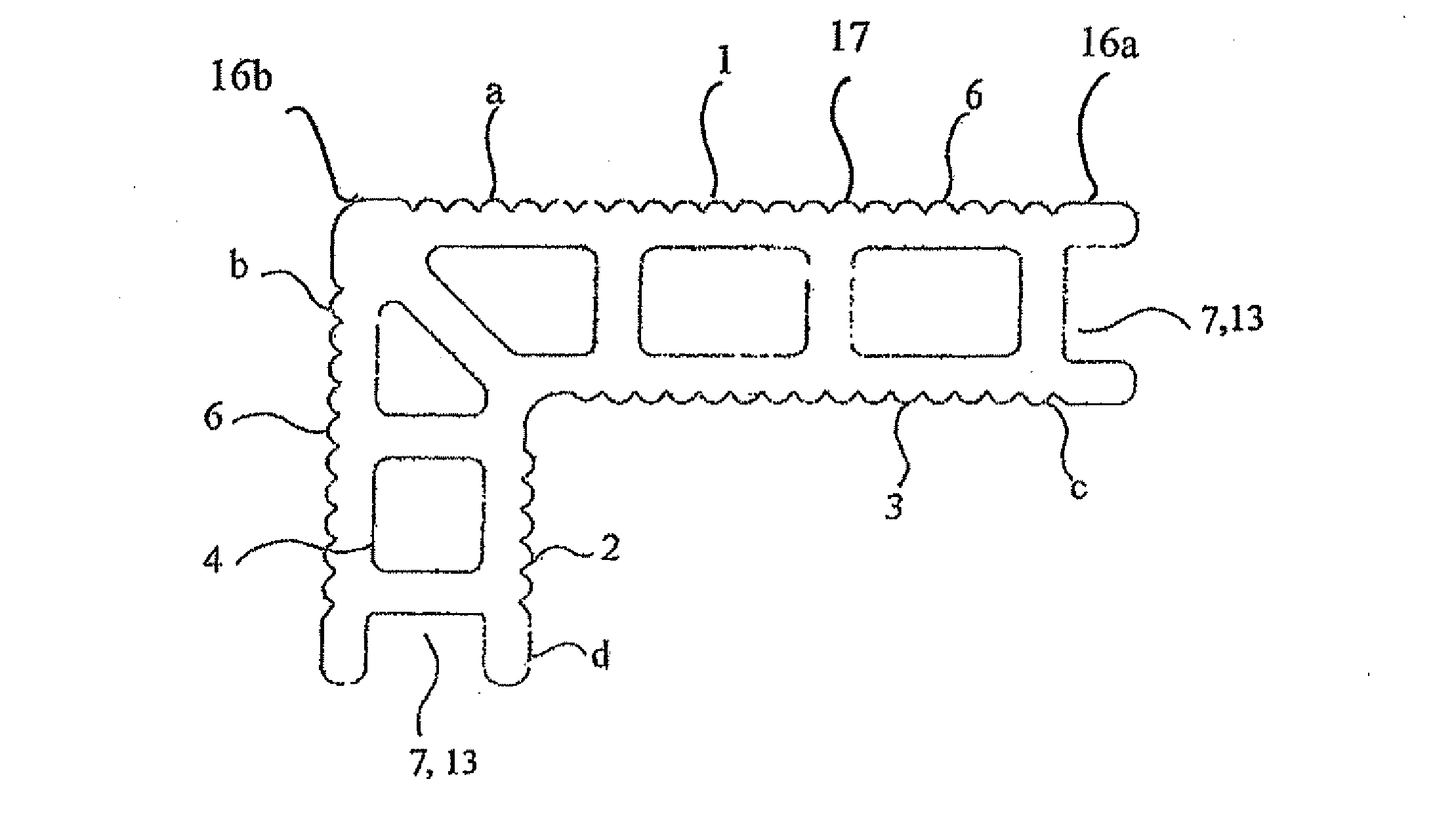
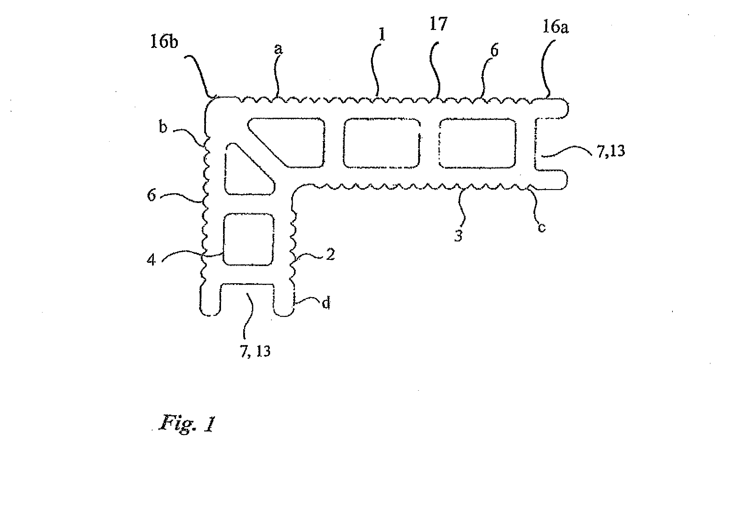
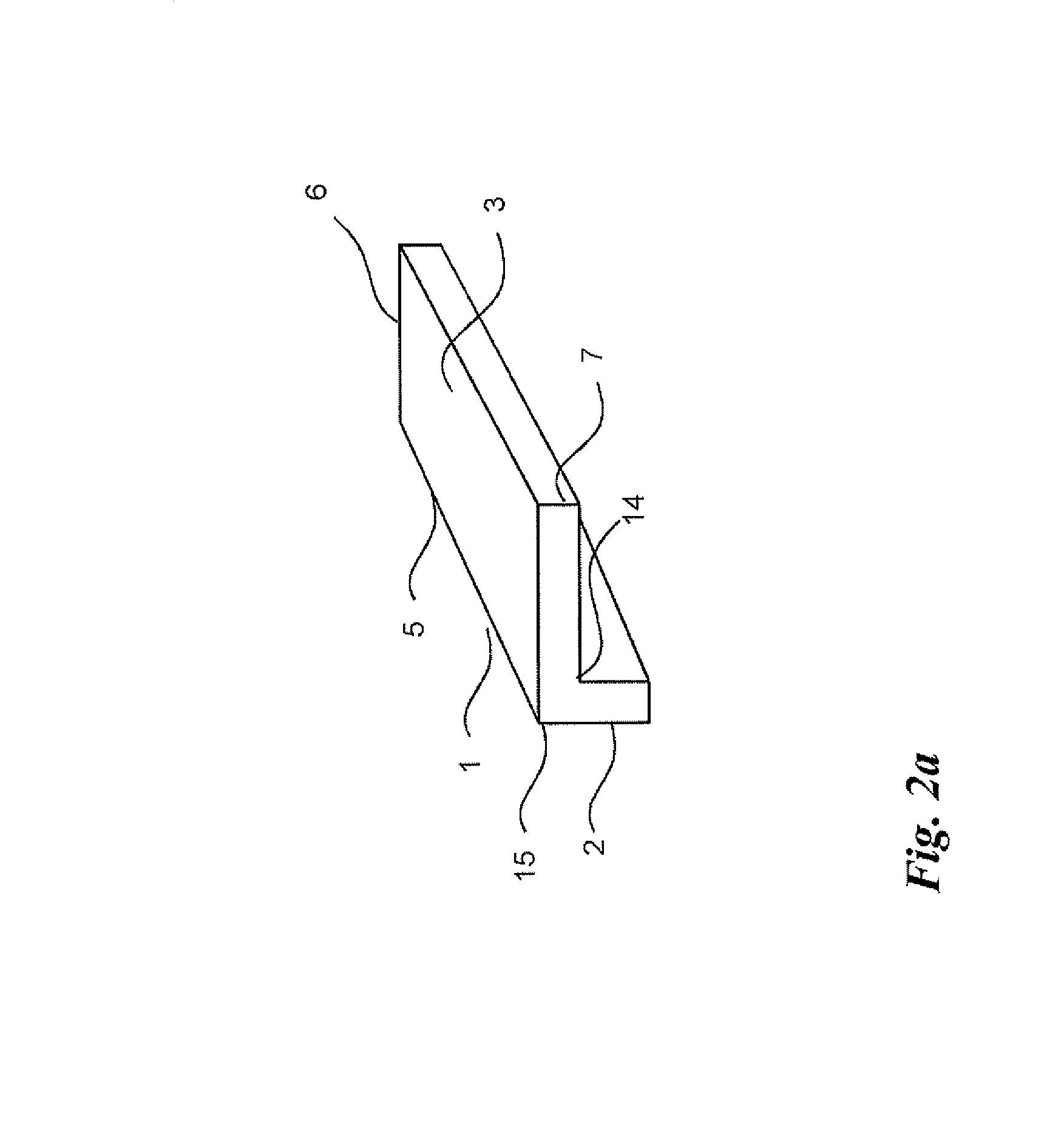
[0064]The L-profile shaped element 1 illustrated in FIGS. 1 and 2a was formed from a wood-plastic composite material. The wood-plastic composite material was mainly formed from adhesive laminate waste. Polypropylene had been added to the adhesive laminate waste. The L-profile shaped element was formed as a monolithic piece by extrusion.

[0065]The L-profile shaped element 1 according to FIGS. 1 and 2a includes a first 2 and a second 3 leg, wherein the legs are arranged to have different widths 6 but the same thicknesses 7. The thickness 7 of the legs 2 and 3 is 28 mm in this embodiment. In this embodiment the width of the outer surface b of the leg in the first leg 2 is 68 mm and the width of the inner surface d is 40 mm. The width of the outer surface a of the leg in the second leg 3 is 110 mm and the width of the inner surface c is 82 mm. The length 5 of the L-profile shaped element 1 may vary depending on the purpose of use of the element.

[0066]An interior angle 14 and an exterior ...

example 2

[0072]FIG. 3 illustrates a stair structure formed from the L-profile shaped elements 1 according to Example 1.

[0073]The L-profile shaped elements 1 according to Example 1 are fitted in predetermined positions, in this case alternately both ways around in order to achieve an optimum rise and optimum run for the steps of the stair structure of this embodiment. The L-profile shaped element 1 forms together with another L-profile shaped element 1 the rise part 11 of the step and the tread 12.

[0074]Each L-profile shaped element is arranged to be joined from at least one thicknesswise end 7 of the leg to at least one thicknesswise end of the leg of another L-profile shaped element.

[0075]The joints between the elements are provided to the middle of the tread 12 or the rise part 11.

example 3

[0076]FIG. 4 illustrates a stair structure formed from the L-profile shaped elements 1 according to Example 1.

[0077]The L-profile shaped elements 1 according to Example 1 are fitted in predetermined positions, in this case alternately both ways around in order to achieve the optimum rise and optimum run for the steps of the stair structure of this embodiment. The L-profile shaped element 1 forms together with another L-profile shaped element 1 the rise part 11 of the step and the tread 12.

[0078]Each L-profile shaped element is arranged to be joined from at least one thicknesswise end of the leg to at least one thicknesswise end of the leg of another L-profile shaped element.

[0079]The joints between the elements are provided to the middle of the tread 12 or the rise part 11.


PUM

PropertyMeasurementUnit
Angleaaaaaaaaaa
Widthaaaaaaaaaa
Areaaaaaaaaaaa

Abstract

An L-profile shaped element is formed as a monolithic piece, and the L-profile shaped element includes a first and a second leg, wherein the legs are arranged to have substantially the same thicknesses, at least one edge of each leg is provided with joint parts functioning in the substantially same manner, and the element is turnable to a desired position. In addition, the invention relates to the use of the L-profile shaped element and to a method for installing L-profile shaped elements.

Description

FIELD OF THE INVENTION[0001]The invention relates to the L˜profile shaped element defined in the preamble of claim 1, to the uses defined in the preambles of claims 17 and 18, and to the methods for installing the L-profile shaped element defined in the preambles of claims 19 and 24.BACKGROUND OF THE INVENTION[0002]Known from the prior art are different floor, ceiling and wall elements formed from a composite material for both interior and exterior use. Composite materials have lately become more general in the manufacture of different surface elements by virtue of their easy maintenance, tailored weather-resistance and new color palette.[0003]Furthermore, it is known to use different edge strips in connection with floor or terrace structures formed from a composite material to finish the visual look. However, a problem in the use of the known edge strips is that they are easily loosened and seldom withstand intensive wear and use.[0004]In addition, known from the prior art are diff...

Claims


Application Information

Patent Timeline
IPC IPC(8): E04C2/30
CPCE04F11/116Y10T29/49826E04C2/30E04F11/16E04F11/09E04F11/1043E04F11/17E04F15/105E04F19/061E04F2203/04
Inventor LEHTINEN, LIISALATIKKA, HARRI
Owner UPM-KYMMENE OYJ
Why Eureka
Try Eureka