
Baler Attachment for Optionally Changing the Orientation of Bales Being Released From a Baler

a baler and optional technology, applied in the field of baler attachment, can solve the problems of inconvenient operation, inconvenient operation, and inefficient weaving throughout the field

Active Publication Date: 2013-03-28
VERMEER MFG CO
View PDF5 Cites 23 Cited by
  • Summary
  • Abstract
  • Description
  • Claims
  • Application Information

AI Technical Summary

Benefits of technology

The patent describes a device that allows a bale to be caught and rested on a platform without rolling on the ground. This is achieved by using a bale catching arm that is attached to the baler frame and the bale moves off of the carriage. The catching arm has a cylindrical axis with a top and bottom, and the arm stops the bale from rolling on the ground as it moves. The technical effect of this device is that it ensures the bale moves safely and securely during the processing of agricultural crop material.

Problems solved by technology

Since typically round bales are ejected from the baler with their axis perpendicular to the direction of travel, this means that current standard retrieval machines must also travel perpendicular to the field rows to line up with the bales and weave inefficiently throughout the field to get to each bale.
In row crops, this also results in travelling across the field rows which is bumpy and can be uncomfortable for the operator and damaging to the equipment.
Some current retrievers attempt to address this by twisting the bale on the field during pickup, but crops like corn stover bales on corn stubble fields can and are often damaged by this process resulting in a loss of the bale.
Additionally, if round bales are ejected on a slope such as hillsides they can roll downhill and be damaged or cause a dangerous situation.
Operators try to compensate for this by manipulating the tractor / baler combination manually before ejecting the bale, but this process is time consuming and inaccurate.
Another reason to have the combine go parallel to the rows is that it would be a very bumpy ride to travel across each ridge of each row.
As mentioned above, loading those round bales dropped in a corn field to transport them from the corn field cannot be efficiently accomplished by merely traveling parallel to the corn rows because loading equipment requires that the bales be approached from the ends and not from the rounded sides.
But the prior art bale turners are not entirely suitable for use in row crop fields such as corn fields.
GB 2 292 335 to Rout uses ground engaging carriage wheels on his bale turner, which would not work well when crossing ridges between rows in a harvested corn field but would cause the carriage to bounce up and down when crossing the ridges.

Method used


Image

  • Baler Attachment for Optionally Changing the Orientation of Bales Being Released From a Baler
  • Baler Attachment for Optionally Changing the Orientation of Bales Being Released From a Baler
  • Baler Attachment for Optionally Changing the Orientation of Bales Being Released From a Baler

Examples


Embodiment Construction

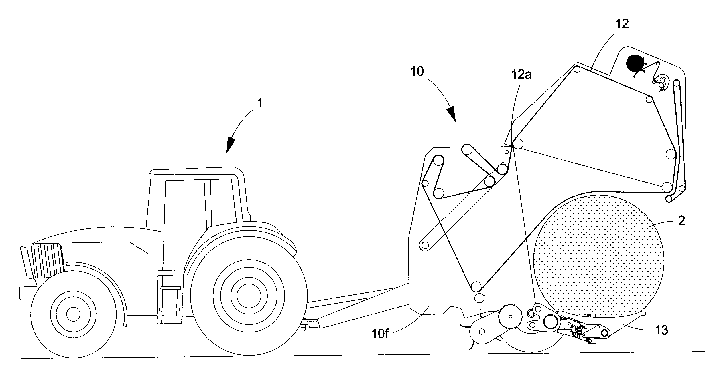
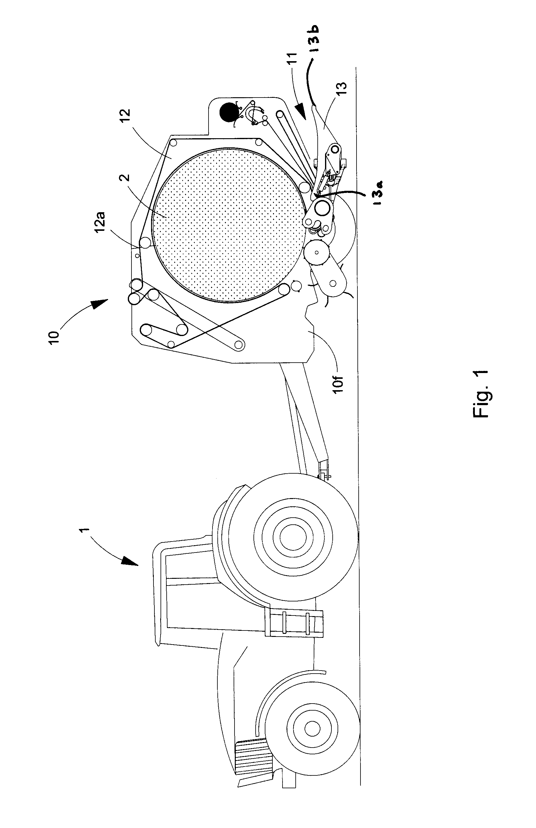
[0061]Referring now to the drawings, wherein like reference numerals indicate identical or similar parts throughout the several views, FIG. 1 shows a baler 10 being towed by a tractor 1, in the process of making a bale 2, the baler 10 having a bale turning apparatus 11 attached thereto.

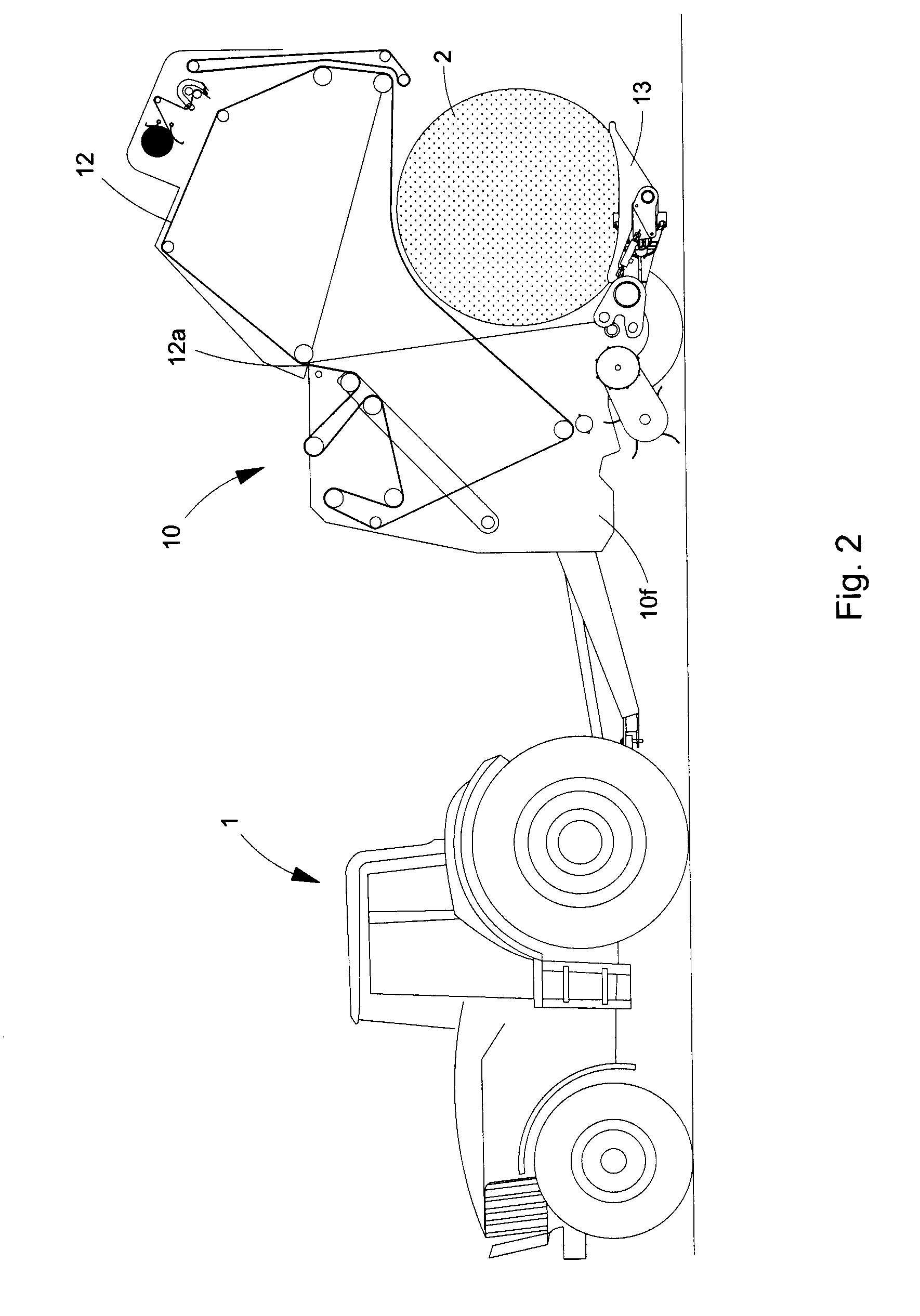
[0062]After the bale 2 has been completed, the rear gate 12 is pivoted up about horizontal axis 12a as shown in FIG. 2, allowing the bale to move rearwardly onto a cradle 13 which is part of turning device 11 of the present invention.

[0063]FIGS. 3-5 show sequentially the next few steps of how the present invention operates in two of its most useful modes, FIG. 3 showing the FIG. 2 position with the bale 2 resting on cradle 13. Then, the bale turning apparatus 11 pivots the cradle 13 and bale 2 ninety degrees (90°) along vertical axis 13v to a position to one side of the baler 12 as shown looking from the tractor 1 in FIG. 4 and looking from the rear of the baler in FIG. 5.

[0064]FIG. 6 is an alternate ...


PUM


Abstract

A bale turning apparatus for attachment to a baler to generally align the cylindrical of the bales in each row as the bales are released from the baler. Using the disclosed invention, the bales are essentially turned ninety degrees from the orientation of bales from the position that they are typically released from a round baler. By accomplishing this general alignment of the cylindrical axis of each bale in each row, when baling corn stover or other row crops, the bale loading operation can later be done more efficiently by driving down the rows in the same direction as the combine and baler have traveled.

Description

TECHNICAL FIELD[0001]This invention relates generally to balers and more particularly to an attachment for balers for controlling the orientation of bales when such bales are released from the baler onto the ground.BACKGROUND[0002]As forage material comes into a baler for making round bales, the material turns in the baling chamber around a rotational axis of formation, or the eventual cylindrical axis of the bale, which axis is transverse to the direction of forward travel of the baler as the bale is being formed. So when the bales are released from the rear of the baler, the cylindrical axis of the bale is still transverse to the direction of forward travel of the baler.[0003]Since typically round bales are ejected from the baler with their axis perpendicular to the direction of travel, this means that current standard retrieval machines must also travel perpendicular to the field rows to line up with the bales and weave inefficiently throughout the field to get to each bale. In r...

Claims


Application Information

Patent Timeline
IPC IPC(8): A01F15/08
CPCA01F15/0883A01D90/10A01F15/07
Inventor THOMPSON, KENT L.DUX, DARIN L.OLMSTEAD, JUSTIN D.
Owner VERMEER MFG CO
Learn More