Display shelf with adjustable divider walls

a technology of divider walls and shelves, applied in the field of shelving systems, can solve the problems of elongating the divider wall, and reducing the efficiency of employees tasked with reconfiguring the channel width, etc., to achieve the effect of effectively resisting lateral loads, increasing the stiffness of the divider wall, and reversed engagement process

Inactive Publication Date: 2013-03-28
B O F
View PDF16 Cites 29 Cited by
  • Summary
  • Abstract
  • Description
  • Claims
  • Application Information

AI Technical Summary

Benefits of technology

[0007]The wall portion may also include a rigidifying portion that increases the bending stiffness of the wall portion. More specifically, the rigidifying portion reduces transverse deformation or bending of the wall portion when the wall portion is subjected to transverse loads. The rigidifying portion may longitudinally extend along the entire length of the wall portion, or the rigidifying portion may extend along one or more longitudinal segments of the wall portion. The rigidifying portion may include a top oblique portion that obliquely extends from the first surface of the wall portion such that the top oblique portion forms an obtuse angle with a top planar portion. The rigidifying portion may also include a bottom oblique portion that obliquely extends from the first surface of the wall portion such that the bottom oblique portion forms an obtuse angle with a bottom planar portion, wherein the bottom planar portion and the top planar portion are each bisected by a longitudinal plane. An intermediate planar portion may extend between the inwardly-disposed ends of the top oblique portion and the bottom oblique portion such that the intermediate planar portion is transversely offset from both the top planar portion and the bottom planar portion. In another embodiment, the rigidifying portion may include a single intermediate oblique portion that obliquely extends from the first surface of the wall portion such that the intermediate oblique portion forms an obtuse angle with the bottom planar portion. A top planar portion may extend from an end of the intermediate oblique portion such that the top planar portion is parallel to and transversely offset from the bottom planar portion.
[0016]When the first front leg and the rear leg (and, if applicable, the intermediate leg or legs) are fully inserted into the front slot and the rear slot (and the intermediate slot or slots), respectively, the divider wall is released and is allowed to displace towards the front end of the shelf assembly under the influence of (or with the assistance of) gravity. Eventually, a portion of the perimeter surface that is bounded by the first side edge of the first front leg comes into contact with a forward wall that partially defines the front slot, thereby preventing further forward displacement of the divider wall within the slot. At this time, a portion of the perimeter surface that is bounded by the first side edge of the rear leg may come into contact with (or may be closely adjacent to) a forward wall that defines the rear slot, and, if appropriate, a portion of the perimeter surface that is bounded by the first side edge of each of the intermediate legs may come into contact with (or may be closely adjacent to) a forward wall that defines each of the intermediate slots. So positioned, an undersurface of the shelf assembly adjacent the front slot is in contact with or immediately adjacent to the engagement protrusion of the first front leg. More specifically, the undersurface of the shelf assembly is in contact with or immediately adjacent to the portion of the perimeter surface that is bounded by the top engagement edge of the engagement protrusion. With the undersurface in contact with or immediately adjacent to the top engagement edge of the engagement protrusion, the divider wall is prevented from upwardly displacing relative to the shelf assembly, thereby securing the divider wall to the shelf assembly.
[0019]So positioned, the undersurface of the shelf assembly adjacent the front slots is in contact with or immediately adjacent to the engagement protrusion of each of the first front leg and the second front leg. More specifically, the undersurface of the shelf assembly is in contact with or immediately adjacent to the portion of a perimeter surface that is bounded by the top engagement edge of the each of the engagement protrusions of the first front leg and the second front leg. With the undersurface in contact with or immediately adjacent to the top engagement edges of the engagement protrusions, the divider wall is prevented from upwardly displacing relative to the shelf assembly, thereby securing the divider wall to the shelf assembly. To disengage the divider wall from the shelf assembly, the engagement process is reversed.
[0020]When secured to the shelf assembly as described, the engagement protrusion prevents the accidental or inadvertent disengagement of the divider wall from the shelf assembly. In addition, the rigidifying portion that horizontally extends along the wall portion increases the stiffness of the divider wall to more effectively resist lateral loads caused by shifting containers while maintaining an ultra-thin profile. In addition, the use of both a first front leg and a second front leg increases the engagement strength between the divider wall and the shelf assembly to effectively prevent damage to or disengagement of the divider wall when relatively large containers subject the divider wall to lateral loads.

Problems solved by technology

This process of calculating channel widths and repositioning divider walls is time consuming, especially considering the large number of shelves that are typically restocked or reconfigured each day at retail food outlets.
Typically, it is time-consuming to engage and disengage the divider walls using conventional securing mechanisms, thereby reducing the efficiency of the employees tasked with reconfiguring the channel widths.
Such elongate divider walls offer little resistance to lateral (i.e., normal to the wall or rod) loads that result from the shifting of larger containers, such as gallons of milk.
As such, divider walls may laterally deform, or “bow,” resulting in the lateral shifting of containers in the longitudinal channels, creating a disorganized visual product presentation to the consumer and also potentially disrupting the flow of containers in adjacent channels.
In addition, significant lateral loads may permanently deform the divider wall, requiring the repair or replacement of the damaged divider wall.

Method used


Image

  • Display shelf with adjustable divider walls
  • Display shelf with adjustable divider walls
  • Display shelf with adjustable divider walls

Examples


Embodiment Construction

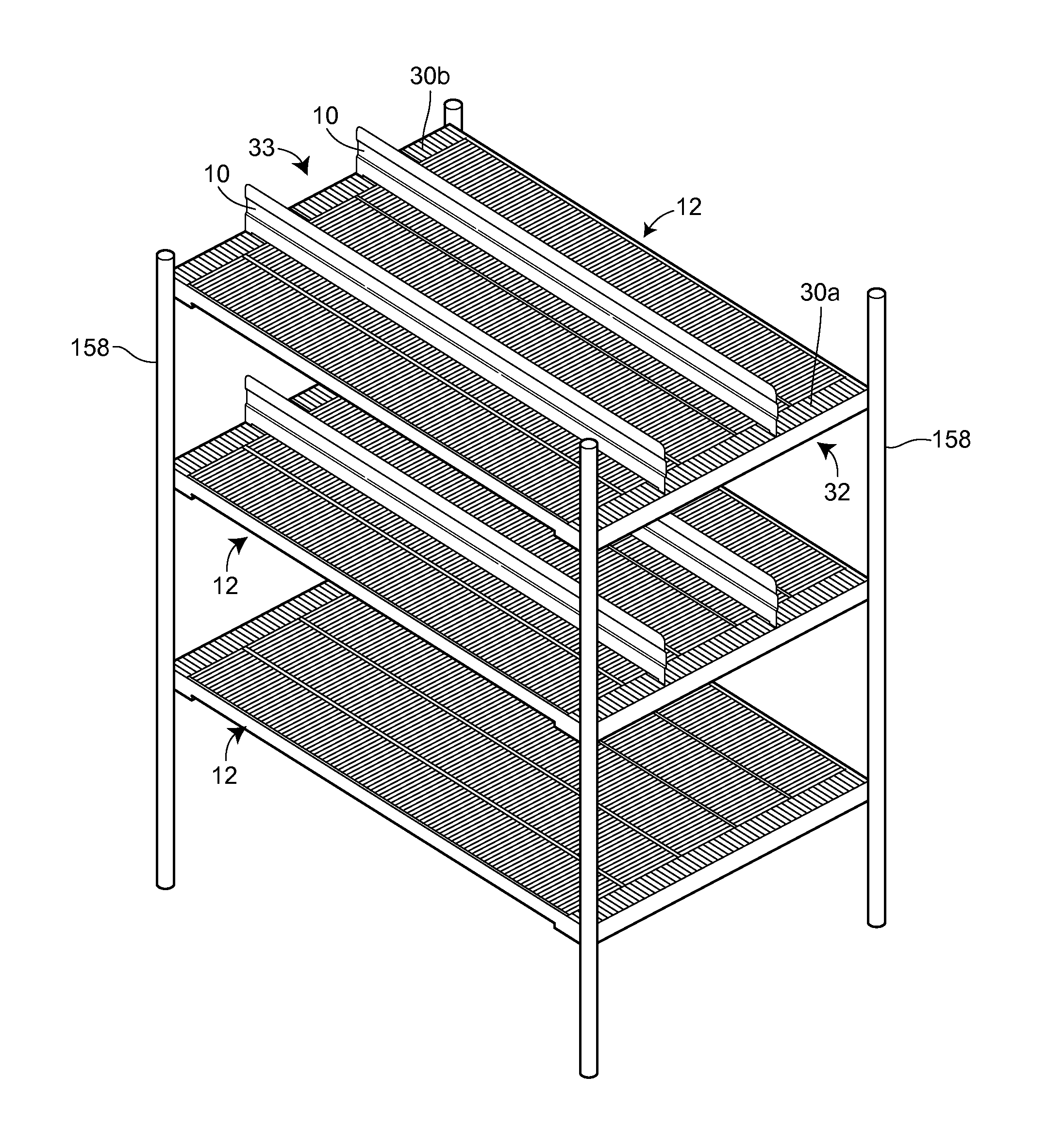
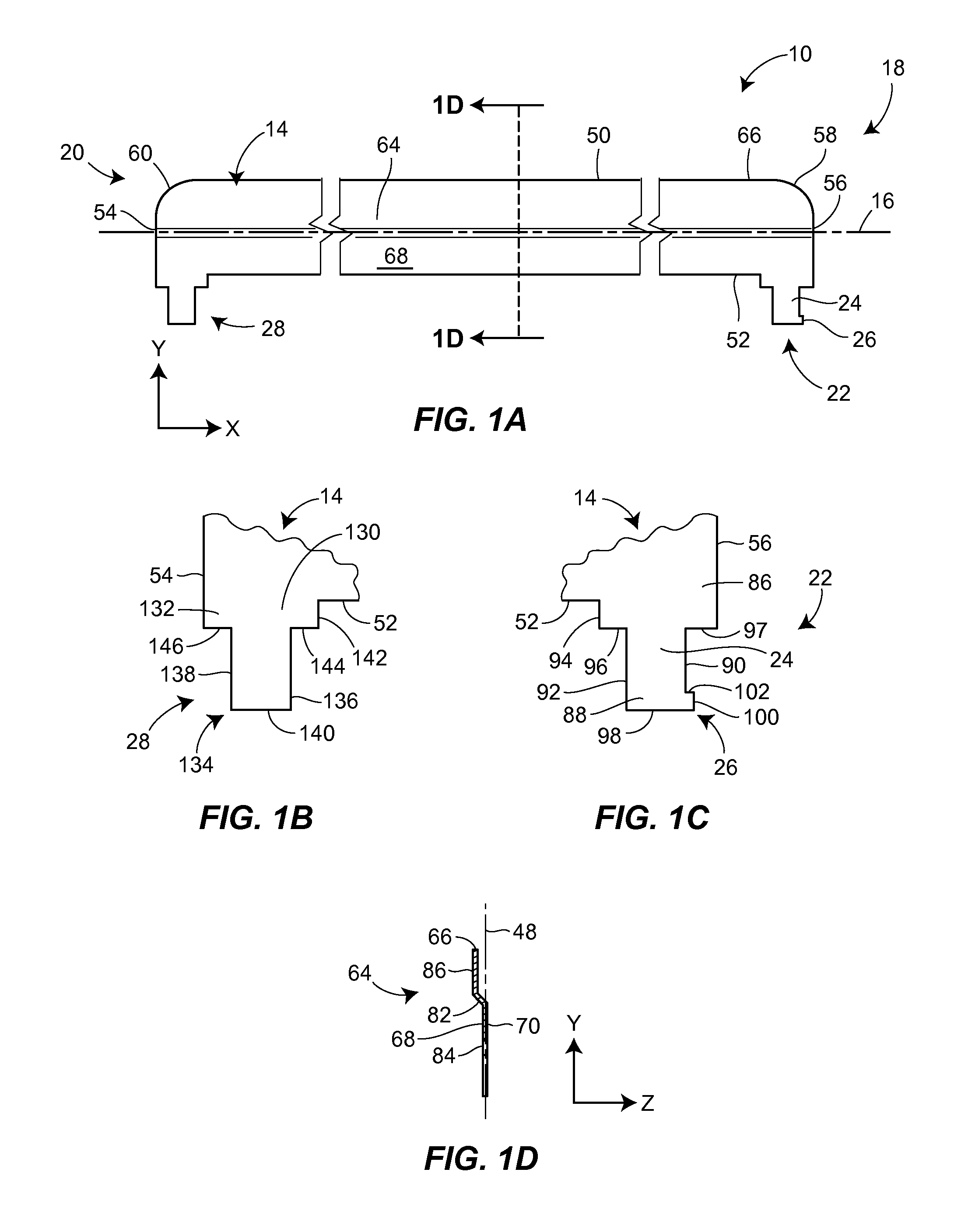
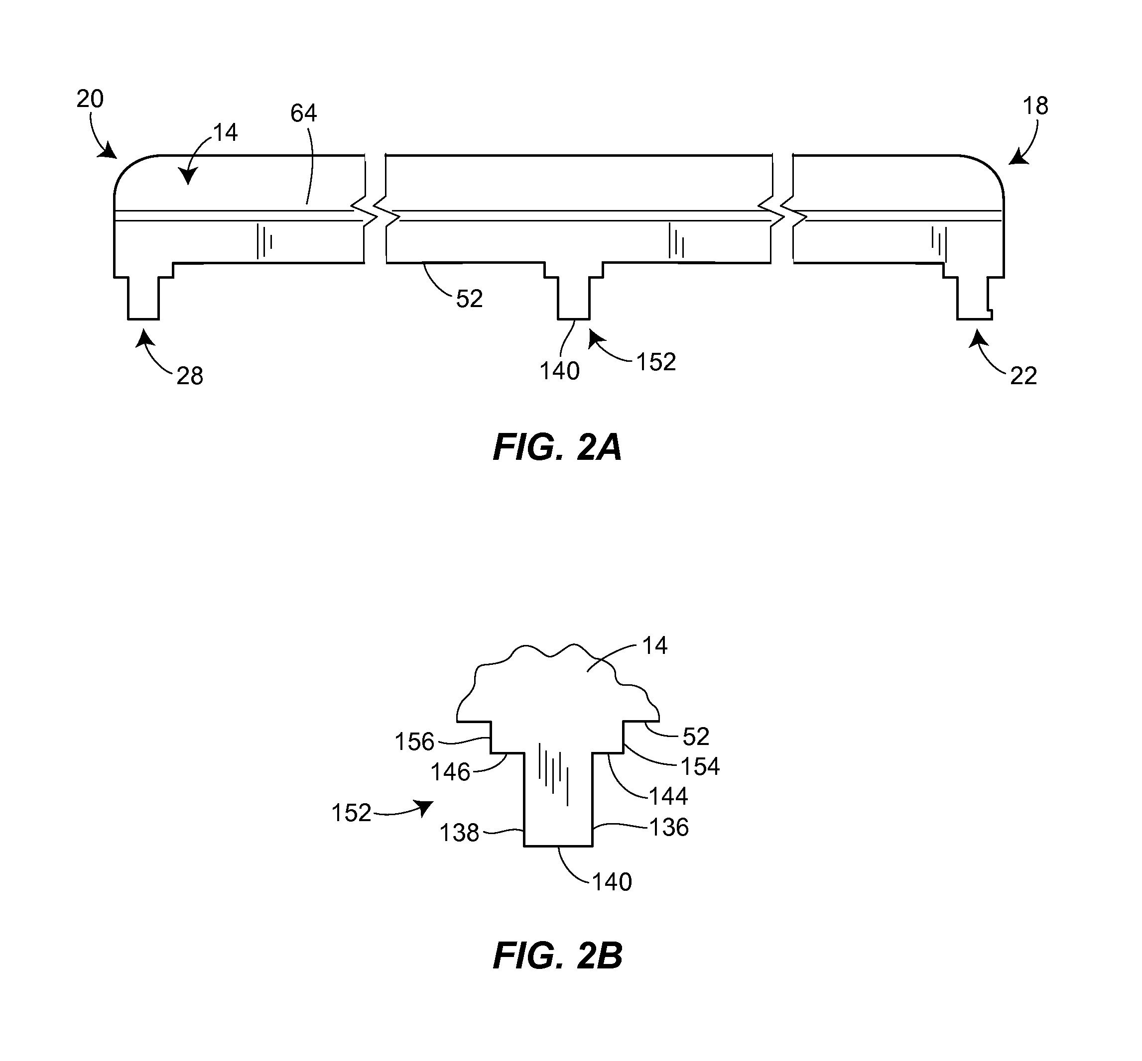
[0048]As illustrated in FIG. 1A, a divider wall 10 for use with a gravity-fed shelf assembly 12 includes an elongate wall portion 14 extending along a longitudinal axis 16, the wall portion 14 having a first end 18 and a second end 20. The divider wall 10 also includes a first front leg 22 extending from the wall portion 14 adjacent the first end 18, the first front leg 22 extending normal to the longitudinal axis 16 of the wall portion 14, the first front leg 22 having a body portion 24 and an engagement protrusion 26 extending from the body portion 24, the engagement protrusion 26 extending in a direction parallel to the longitudinal axis 16 towards the first end 18 of the wall portion 14. The divider wall 10 further includes a rear leg 28 extending from the wall portion 14 adjacent the second end 20, the rear leg 28 extending normal to the longitudinal axis 16 of the wall portion 14.

[0049]As illustrated in FIGS. 5 and 7A to 7D, the first front leg 22 is adapted to be received int...


PUM


Abstract

A divider wall for use with a gravity-fed shelf assembly includes an elongate wall portion and a first front leg extending from a first end of the wall portion. The first front leg has a body portion and an engagement protrusion extending from the body portion. The divider wall further includes a rear leg extending from a second end of the wall portion. The first front leg and the rear leg are each adapted to be received into a front slot and a rear slot, respectively, of the shelf assembly. Gravity acts on the divider wall and displaces it within the front and rear slots toward a front end of the shelf assembly such that an undersurface of the shelf assembly adjacent the front slot is in contact with or immediately adjacent to the engagement protrusion to prevent the removal of the first front leg from the front slot.

Description

FIELD OF THE DISCLOSURE[0001]This disclosure relates generally to shelving systems and, more particularly, to divider walls that are removably coupled to shelf assemblies of such shelving systems.BACKGROUND OF THE INVENTION[0002]Gravity-flow shelving systems are commonly used in retail food outlets to both store and display consumable items, such as individual-serving food containers or beverage containers. Gravity-flow shelving systems generally include one or more display shelves (also called shelf assemblies) supported by a support frame, and each such shelf assembly is inclined relative to a horizontal plane such that items stored on the shelf assembly slide towards a visible and accessible area at the front of the shelf assembly. Each shelf assembly may have a plurality of channels that are formed by divider walls disposed along the length of the shelf assembly. The width of each of the channels may correspond to the width of the containers stored on the respective channel of t...

Claims


Application Information

Patent Timeline
Patent Type & Authority Applications(United States)
IPC IPC(8): A47F1/04A47B23/00A47B96/04
CPCB65G1/023A47F5/005
Inventor MITTEN, J. PATRICKCORETTI, JR., JOSEPHHAMMAC, SCOTT R.GROHOLSKI, TRACY M.
Owner B O F
Why Eureka
Try Eureka