
Stabilizer Torque Box Assembly and Method

a technology of stabilizer and torque box, which is applied in the direction of spars/stringers, manufacturing tools, braids, etc., can solve the problems of reducing the production efficiency of stabilizers, limiting or preventing fabrication and processing techniques, and increasing the weight of known horizontal and vertical stabilizer designs

Inactive Publication Date: 2013-03-28
THE BOEING CO
View PDF5 Cites 33 Cited by
  • Summary
  • Abstract
  • Description
  • Claims
  • Application Information

AI Technical Summary

Benefits of technology

The patent describes an improved design for stabilizer torque box assemblies in vehicles that provide advantages over existing designs. The new design includes a separation ply layer reinforcing the inner braided thermoplastic tube to prevent loss of structural loading capability. Additionally, the design includes one or more braided thermoplastic tubular truss ribs and connection assemblies for added strength and stability. Overall, this design improves the performance and durability of stabilizer torque box assemblies in vehicles.

Problems solved by technology

However, such known horizontal and vertical stabilizer designs may have an increased weight due to the multiple stringers and ribs used to stabilize the skin (e.g., prevent skin buckling due to compression loads).
However, where the stringers are eliminated, the structural arrangement may require the addition of intermediate spars which may eliminate any weight savings provided by the honeycomb sandwich structure used between the ribs and spars.
In addition, known methods and systems for fabricating and installing aircraft horizontal or vertical stabilizers include manual methods and systems and typically require multiple sets of tooling and molding operations.
This may limit or prevent fabrication and processing techniques that use braiding machines to braid thermoplastic composite materials because once parts are assembled together, it may be difficult, if not impossible, to put the assembled parts through the braiding machine.
Moreover, such known methods and systems for fabricating aircraft horizontal or vertical stabilizers may require increased time and increased labor which, in turn, may increase fabrication costs.

Method used


Image

  • Stabilizer Torque Box Assembly and Method
  • Stabilizer Torque Box Assembly and Method
  • Stabilizer Torque Box Assembly and Method

Examples


Embodiment Construction

[0045]Disclosed embodiments will now be described more fully hereinafter with reference to the accompanying drawings, in which some, but not all of the disclosed embodiments are shown. Indeed, several different embodiments may be provided and should not be construed as limited to the embodiments set forth herein. Rather, these embodiments are provided so that this disclosure will be thorough and complete and will fully convey the scope of the disclosure to those skilled in the art.

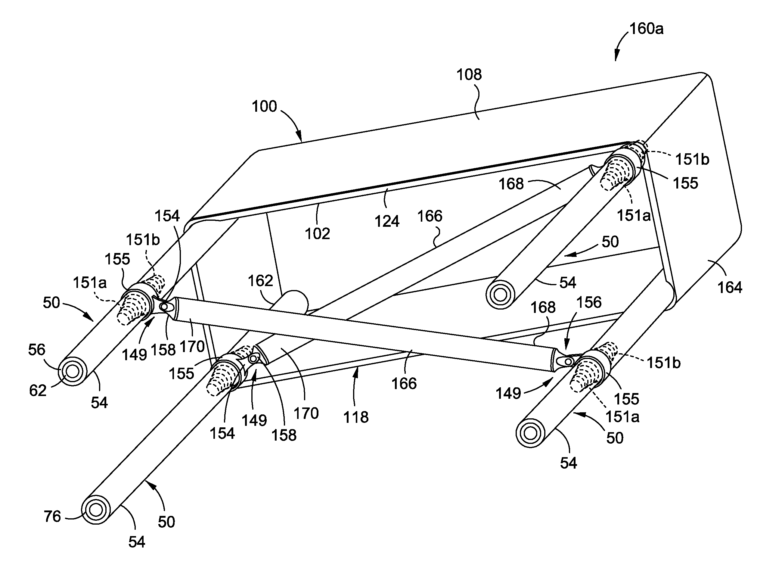
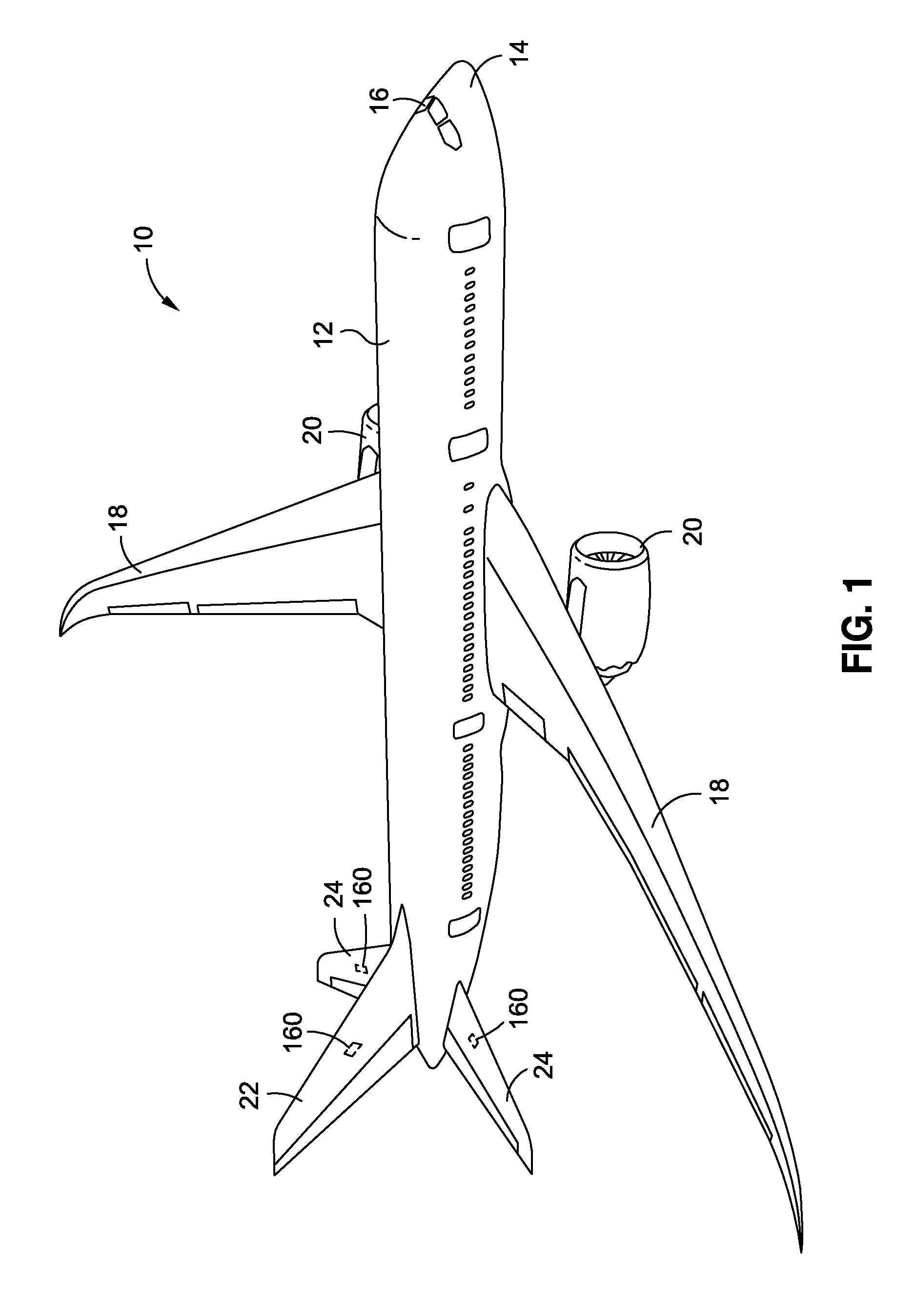
[0046]Now referring to the Figures, FIG. 1 is an illustration of a perspective view of an aircraft 10 which may incorporate one or more advantageous embodiments of a thermoplastic stabilizer torque box assembly 160 and an apparatus 50 to provide a panel stiffening element 52, as disclosed herein. As shown in FIG. 1, the aircraft 10 comprises a fuselage 12, a nose 14, a cockpit 16, wings 18 operatively coupled to the fuselage 12, one or more propulsion units 20, a tail vertical stabilizer 22, and one or mor...


PUM

PropertyMeasurementUnit
tape angleaaaaaaaaaa
torqueaaaaaaaaaa
electrical conductivityaaaaaaaaaa

Abstract

In an embodiment of the disclosure, there is provided an apparatus to provide a panel stiffening element. The apparatus has an outer braided thermoplastic tube and an inner braided thermoplastic tube disposed within the outer braided thermoplastic tube. The apparatus further has a separation ply layer co-consolidated between the outer braided thermoplastic tube and the inner braided thermoplastic tube. The separation ply layer provides reinforcement and impact damage resistance to the inner braided thermoplastic tube in order to avoid a loss in structural loading capability.

Description

BACKGROUND[0001]1) Field of the Disclosure[0002]The disclosure relates generally to stabilizer torque box assemblies and methods, and more particularly, to horizontal and vertical stabilizer torque box assemblies and methods for vehicles.[0003]2) Description of Related Art[0004]Thermoplastic composite structures or parts are used in a wide variety of applications, including in the manufacture of aircraft, spacecraft, rotorcraft, watercraft, automobiles, trucks, and other composite structures. In aircraft construction, thermoplastic composite structures or parts are used in increasing quantities to form the fuselage, wings, tail section, skin panels, and other components. In particular, parts of the aircraft horizontal stabilizers, also known as the horizontal tail, and parts of the aircraft vertical stabilizers, also known as a vertical tail, may be constructed of thermoplastic composite materials.[0005]Known designs exist for aircraft thermoplastic composite and metal horizontal an...

Claims


Application Information

Patent Timeline
Patent Type & Authority Applications(United States)
IPC IPC(8): B64C1/06D04C1/00B23P11/00
CPCB32B1/08Y10T29/49826B64C3/18B32B5/02B32B15/08B32B27/12B32B2307/558B32B2605/00B32B37/02B32B2313/04B32B2311/30B32B2311/24B32B2605/18B32B2307/544B32B2307/202B32B2262/10B32B38/004B32B2311/18B64C3/00B29C70/30B64C1/06Y02T50/40
Inventor MARCOE, JEFFERY LEE
Owner THE BOEING CO
Features
  • Generate Ideas
  • Intellectual Property
  • Life Sciences
  • Materials
  • Tech Scout
  • Unparalleled Data Quality
  • Higher Quality Content
  • 60% Fewer Hallucinations
Learn More