Apparatus, system and method for using an LED to identify a presence of a material in a gas and/or a fluid and/or determine properties of the material

a technology of led and lightemitting diodes, which is applied in the field of apparatus, a system and a method of using led to identify the presence of a material in a gas and/or fluid and/or determine the properties of the material, and can solve the problems of carbon contaminants entering the environment, the equipment to generate ultrasonic pulses for such testing is expensive, and the effect of introducing carbon contaminants

Active Publication Date: 2013-03-28
PHAEDRUS
View PDF8 Cites 18 Cited by
  • Summary
  • Abstract
  • Description
  • Claims
  • Application Information

AI Technical Summary

Benefits of technology

[0028]It is, therefore, an advantage of the present invention to provide an apparatus, a system and a method for using an LED to identify a presence of a material in a gas and / or a fluid.
[0029]Another advantage of the present invention is to provide an apparatus, a system and a method for using an LED to determine properties of a material in a gas and / or a fluid.
[0030]Further, an advantage of the present invention is to provide an apparatus, a system and a method for using an LED to identify a presence of a material in a gas and / or a fluid which use an intensity of light to determine the properties of the material.
[0031]Yet another advantage of the present invention is to provide an apparatus, a system and a method for using an LED to identify a presence of a material in a gas and / or a fluid which determine light reflection, light refraction, light transmission, light diffraction and / or light interference of the material.
[0032]In addition, an advantage of the present invention is to provide an apparatus, a system and a method for using an LED to identify a presence of a material in a gas and / or a fluid which do not use ultrasonic pulses.
[0033]Another advantage of the present invention is to provide an apparatus, a system and a method for using a LED to identify a presence of irregularities in a slurry and determine the properties of the irregularities.

Problems solved by technology

However, equipment to generate ultrasonic pulses for such testing is expensive.
Therefore, ultrasonic testing of slurries is costly.
However, gas bubbles or water in the mineral oil may cause arcing.
Arcing may introduce carbon contaminants into the mineral oil of the transformer.
Gas bubbles, water, and carbon contaminants may impair the ability of the mineral oil to insulate the transformer.
Therefore, these irregularities may cause a transformer to overheat.
Without the lubrication provided by the oil, the moving parts of the aircraft engine directly contact each other and, as a result, degrade rapidly.
For example, ceramic bearings are high performance bearings but are not used in aircraft engines because ceramic shards introduced into the aircraft engine oil cannot be detected using known oil turbidity sensors.
Undetected ceramic shards may impair aircraft engine oil function and typically are not identified until engine trouble occurs.
Therefore, lower performance bearings which create debris detected by known oil turbidity sensors are used in aircraft engines.
Intravenous tubing may deliver an air bubble into the patient's circulation to block a vessel and cause an embolism.
Peripheral intravenous tubing, namely intravenous tubing which uses a short catheter inserted into a peripheral vein, has a low risk of embolism because a large bubble cannot travel through a narrow catheter; however, a greater risk of air bubble-induced embolism is presented by central intravenous tubing.
An embolism may cause life-threatening damage to pulmonary circulation or stop the heart.

Method used


Image

  • Apparatus, system and method for using an LED to identify a presence of a material in a gas and/or a fluid and/or determine properties of the material
  • Apparatus, system and method for using an LED to identify a presence of a material in a gas and/or a fluid and/or determine properties of the material
  • Apparatus, system and method for using an LED to identify a presence of a material in a gas and/or a fluid and/or determine properties of the material

Examples


Embodiment Construction

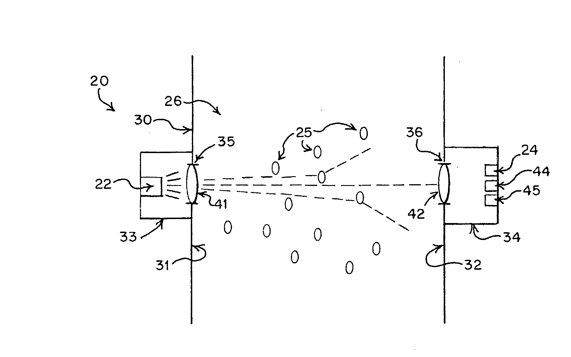
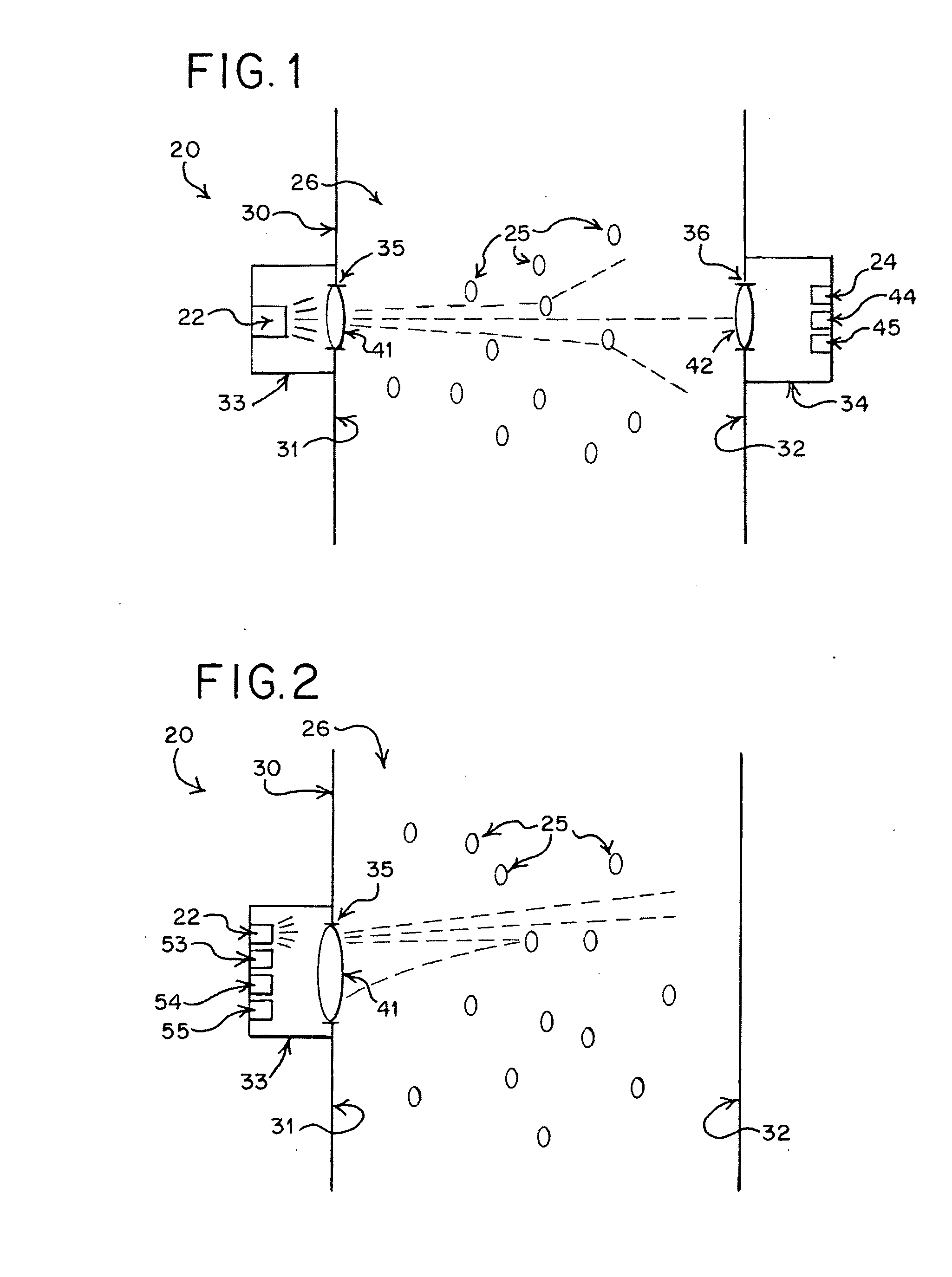
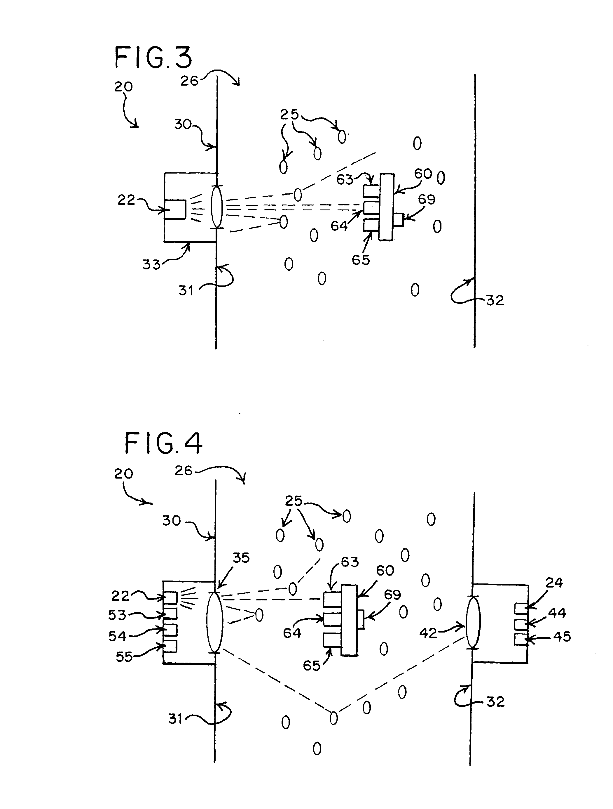
[0048]The present invention generally relates to an apparatus, a system and a method for using a light-emitting diode (LED) to identify a presence of a material in a gas and / or a fluid and / or determine properties of the material. More specifically, the present invention relates to an LED and a light detector that may be used to determine the presence or absence of the material in the gas and / or the fluid and the properties of the material, such as, for example, a refractive index of the material and / or a chemical compound in the material.

[0049]The gas and / or the fluid may be located in a chamber. A first light detector may be positioned on the opposite side of the chamber relative to the LED, a second light detector may be positioned on the same side of the chamber as the LED, and / or a third light detector may be positioned inside the chamber. One or more of the light detectors may be coupled to a first additional light detector having a carbon black coating. One or more of the ligh...


PUM

PropertyMeasurementUnit
timeaaaaaaaaaa
refractive indexaaaaaaaaaa
light transmissionaaaaaaaaaa

Abstract

An apparatus, a system and a method use a light-emitting diode (LED) to identify the presence of a material in a gas and/or a fluid and/or to determine properties of the material. The LED and a light detector may be used to determine a chemical compound in the material. The gas and/or the fluid may be located in a chamber. A first light detector may be positioned on the opposite side of the chamber relative to the LED, a second light detector may be positioned on the same side of the chamber as the LED, and/or a third light detector may be positioned inside the chamber. Additional light detectors with coatings may enable measurements to be corrected for the effects of temperature. The light detectors may determine light reflection, light refraction, light transmission, light diffraction, light interference, light diffusion, light collimation, light absorption and/or light focusing of the material.

Description

BACKGROUND OF THE INVENTION[0001]The present invention generally relates to an apparatus, a system and a method for using a light-emitting diode (LED) to identify a presence of a material in a gas and / or a fluid and / or determine properties of the material. More specifically, the present invention relates to an LED and a light detector that may be used to determine the presence or absence of the material in the gas and / or the fluid and the properties of the material, such as a refractive index of the material and / or a chemical compound in the material.[0002]The presence of a material in a fluid is important for slurries. A slurry is a suspension of solids in a liquid. An example of a commercially implemented slurry is an ethanol slurry made from the fermentation of corn or another starch. Ethanol slurries are used to produce fuels, alcoholic beverages, solvents, and organic reagents. The purity of the slurry may be critical for the subsequent uses of the slurry. It is known to detect...

Claims


Application Information

Patent Timeline
Patent Type & Authority Applications(United States)
IPC IPC(8): G01N21/00
CPCG01N21/31G01N21/41G01N2201/062G01N21/53G01N2021/3181G01N21/45G01N2021/4711G01N2021/516
Inventor ENGSTRAND, BRADLEY W.
Owner PHAEDRUS
Why Eureka
Try Eureka