
Cooling module for cooling electronic components

a technology of electronic components and cooling modules, which is applied in the direction of laminated elements, lighting and heating apparatuses, and semiconductor/solid-state device details, etc., can solve the problems of low transfer coefficient between the fin surface and the air, system cost, and high cost of water cooling systems

Inactive Publication Date: 2013-03-28
ABB RES LTD
View PDF10 Cites 61 Cited by
  • Summary
  • Abstract
  • Description
  • Claims
  • Application Information

AI Technical Summary

Benefits of technology

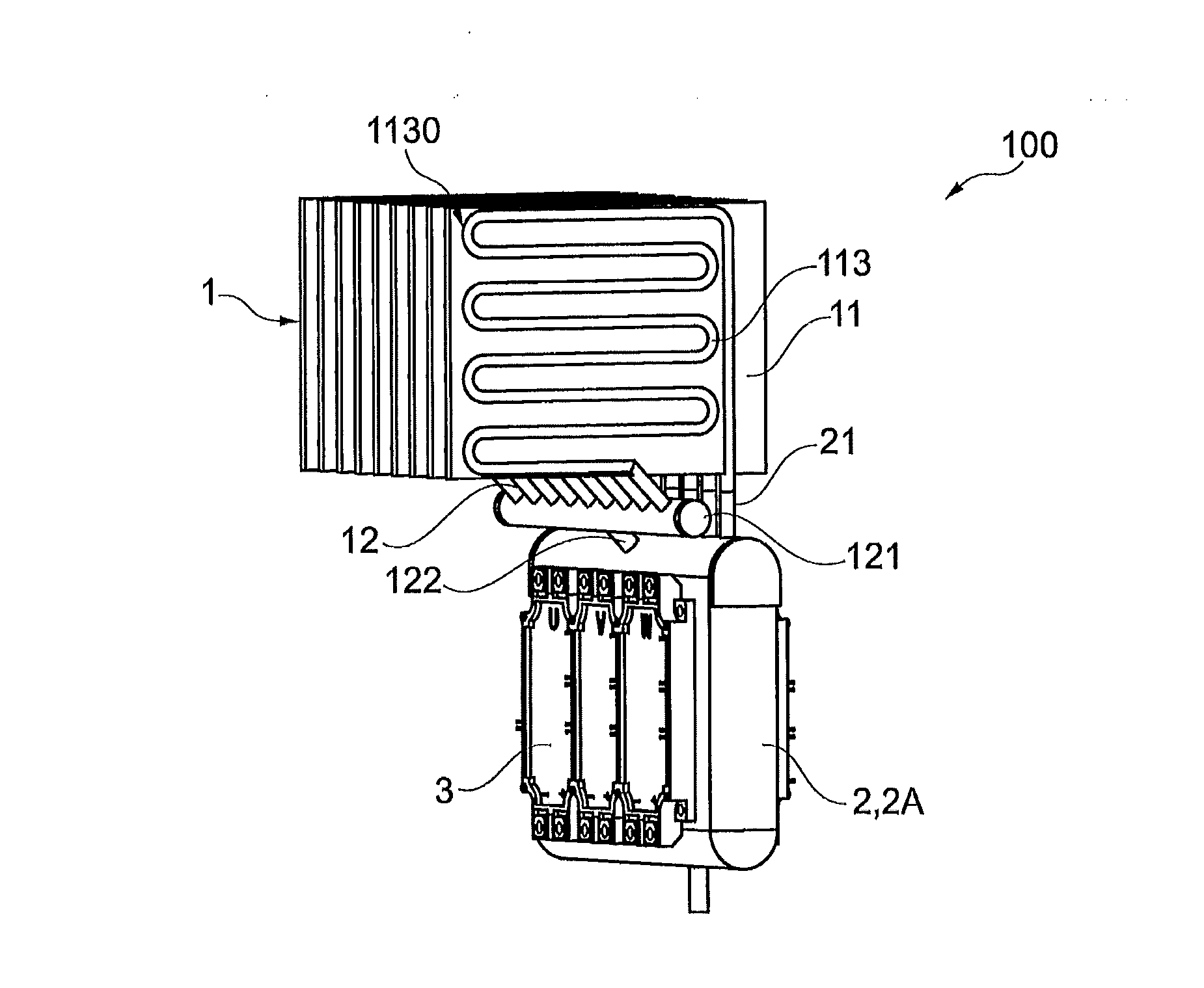
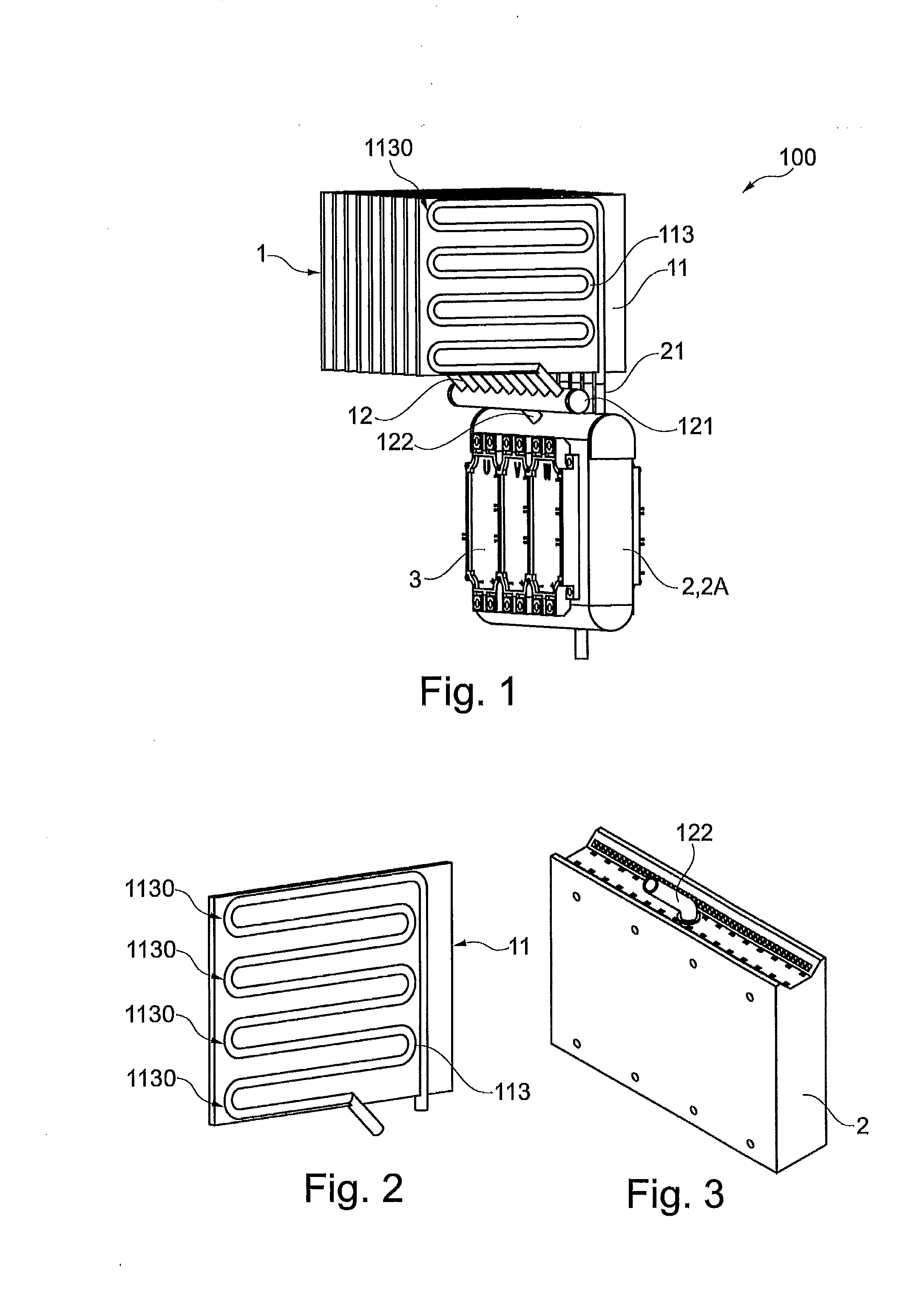
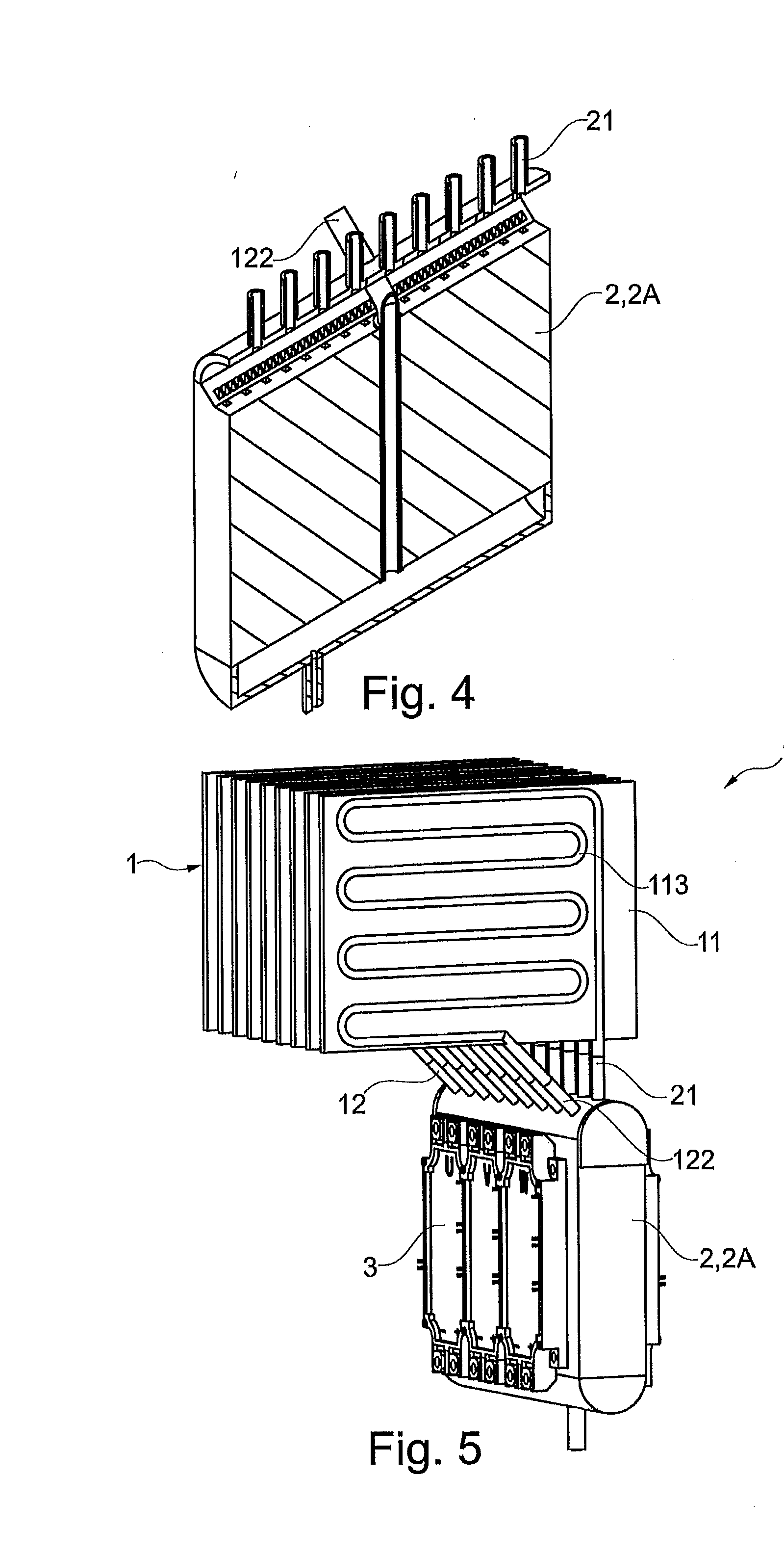
The present invention provides a cooling module for electronic components, including a condenser with two sheets attached to each other by roll-bonding to create a conduit. The module is designed to cool the electronic components by receiving heat from them and transferring it to an ambient environment using a coolant. This invention also includes a power module with a heat receiving unit and the cooling module, as well as a method for cooling electronic components by receiving heat from them and transferring it to the condenser of the cooling module. These technical effects provide improved cooling for electronic components, reducing the risk of damage from overheating.

Problems solved by technology

However, such systems may be costly and may need an active, moving part in the form of a pump, which has a finite life and must be serviced.
Also, water cooling systems are usually quite expensive.
However, as the heat transfer coefficient between fin surface and air is low, a large fin area is required for sufficient cooling performance.
Such designs may result in bulky heat sinks with long, thick, and consequently heavy fins for acceptable fin efficiency.
This drawback may be even made worse if one asks for a minimum spacing between adjacent fins in order to avoid clogging of the inter-fin channels in dirty air environment as may occur in major applications.

Method used


Image

  • Cooling module for cooling electronic components
  • Cooling module for cooling electronic components
  • Cooling module for cooling electronic components

Examples


Embodiment Construction

[0049]Exemplary embodiments of the present disclosure provide an improved, efficient and flexible cooling for electronic and electric components.

[0050]Exemplary embodiments of the present disclosure provide a cooling module, a power module including the cooling module, and a method of cooling electric and / or electronic components. Additional exemplary embodiments are illustrated in the drawings.

[0051]According to an exemplary embodiment of the present disclosure, a cooling module is provided for cooling at least one electronic and / or electronic component. The cooling module includes a condenser which has at least one panel with two sheets that are attached to one another by a process involving rollbonding such that a conduit is formed between the two sheets extending in a direction of a plane formed by the sheets.

[0052]Such a cooling module may have a better performance than a known air cooling or water cooling system and may avoid clogging in a dirty air environment.

[0053]Another p...


PUM


Abstract

A cooling module including a condenser, a power module including the cooling module and a method for cooling electric and / or electronic components are provided. The condenser of the cooling module includes at least one panel for cooling electric and / or electronic components. Two sheets of the panel are attached to one another by a process involving roll-bonding such that a conduit is formed between the two sheets. The conduit extends in a direction of a plane formed by the sheets. Cooling may be provided by evaporating coolant in the conduit at an evaporation section of the panel and by condensing the coolant at a condensing section of the panel. A heat load may be transferred from a heat source to a heat receiving unit. The heat receiving unit is adapted to transfer the heat load to the panel which transfers the heat load to an ambient environment by a thermal carrier.

Description

RELATED APPLICATIONS[0001]This application claims priority as a continuation application under 35 U.S.C. §120 to PCT / EP2010 / 057029, which was filed as an International Application on May 21, 2010 designating the U.S., and which claims priority to European Application 09171455.0 filed in Europe on Sep. 28, 2009. The entire contents of these applications are hereby incorporated by reference in their entireties.FIELD[0002]The disclosure relates to the cooling of electronic and electric components. More particularly, the present disclosure relates to a cooling module including a condenser, a power module including the cooling module, and a method of cooling electric and / or electronic components.BACKGROUND INFORMATION[0003]Cooling systems are widely used in the field of electric, electronic, low, medium and high voltage applications.[0004]Power electronic devices must be cooled in operation, in order to avoid excessive temperatures and consequently failure of the devices. Typical applica...

Claims


Application Information

Patent Timeline
Patent Type & Authority Applications(United States)
IPC IPC(8): H05K7/20F28F1/00
CPCF28D1/035F28D15/0266F28F3/14H01L23/427H05K7/20936H01L2924/0002F28F1/00H01L2924/00F28D15/02H05K7/20
Inventor GRADINGER, THOMASYESIN, BERKAGOSTINI, FRANCESCO
Owner ABB RES LTD
Learn More