
Controller with constant current limit

a technology of constant current limit and controller, which is applied in the direction of pulse automatic control, power conversion system, dc-dc conversion, etc., can solve the problems of longer on-time of the switch and a larger duty ratio

Inactive Publication Date: 2013-03-28
POWER INTEGRATIONS INC
View PDF9 Cites 24 Cited by
  • Summary
  • Abstract
  • Description
  • Claims
  • Application Information

AI Technical Summary

Benefits of technology

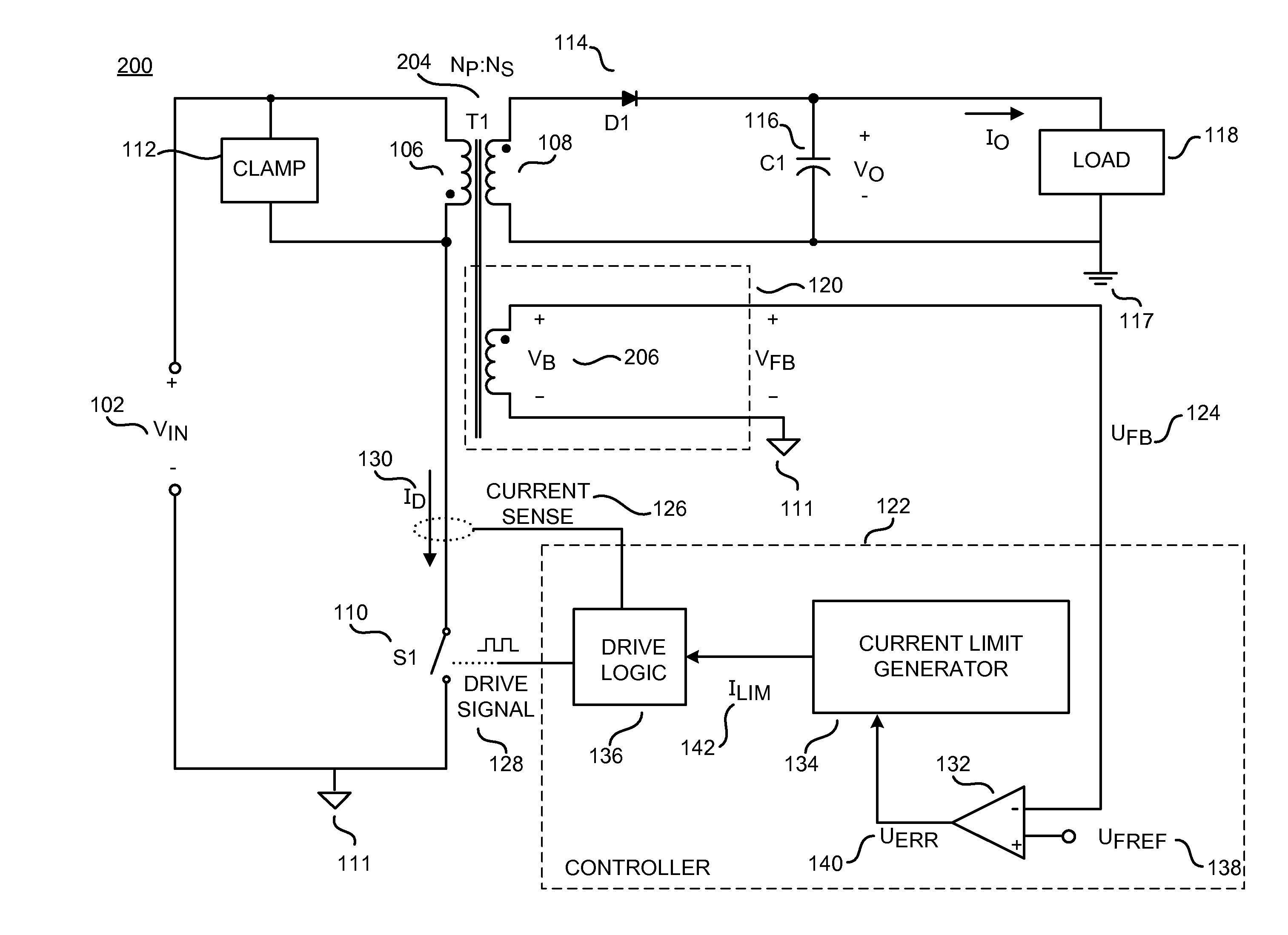
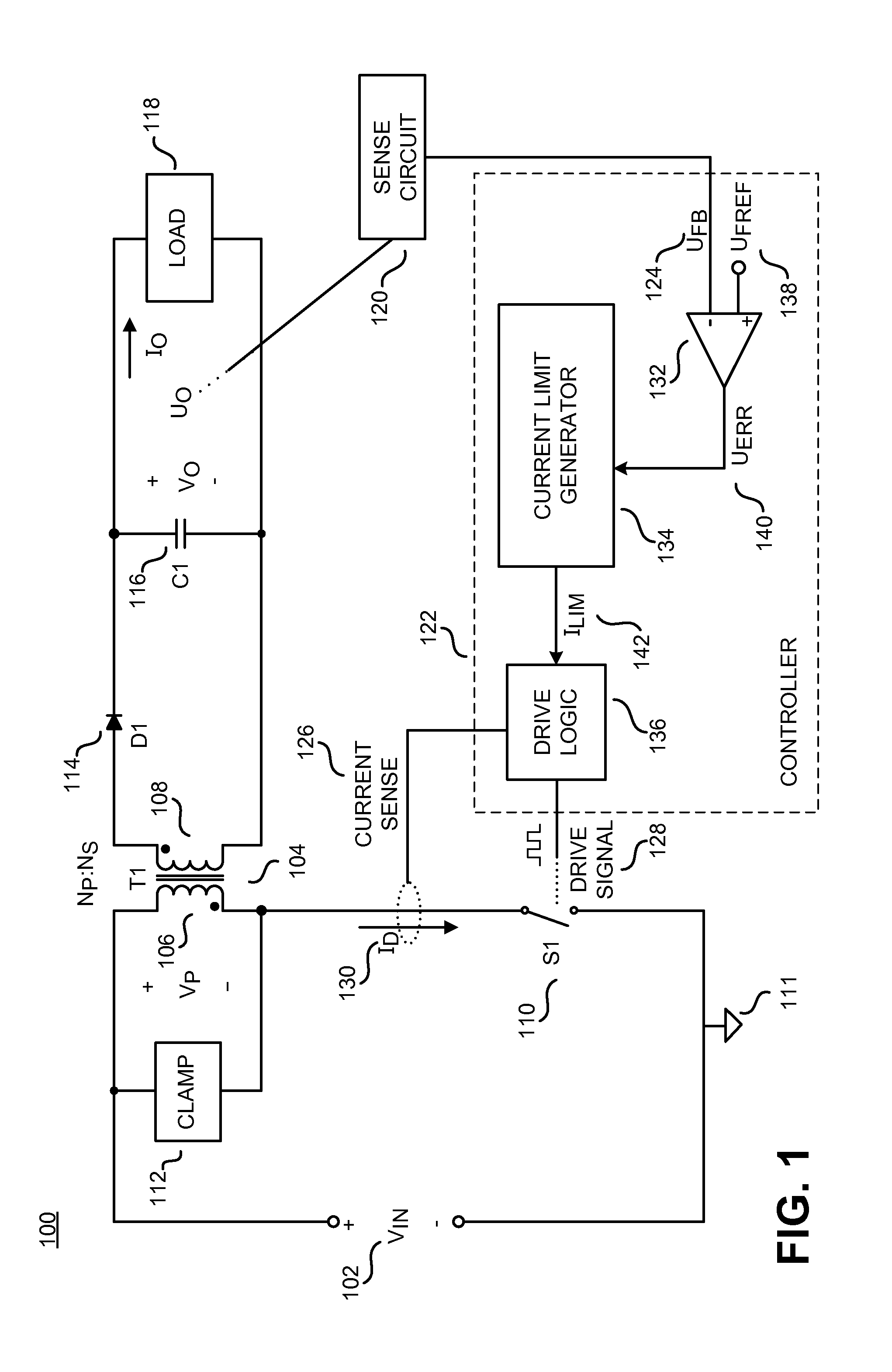
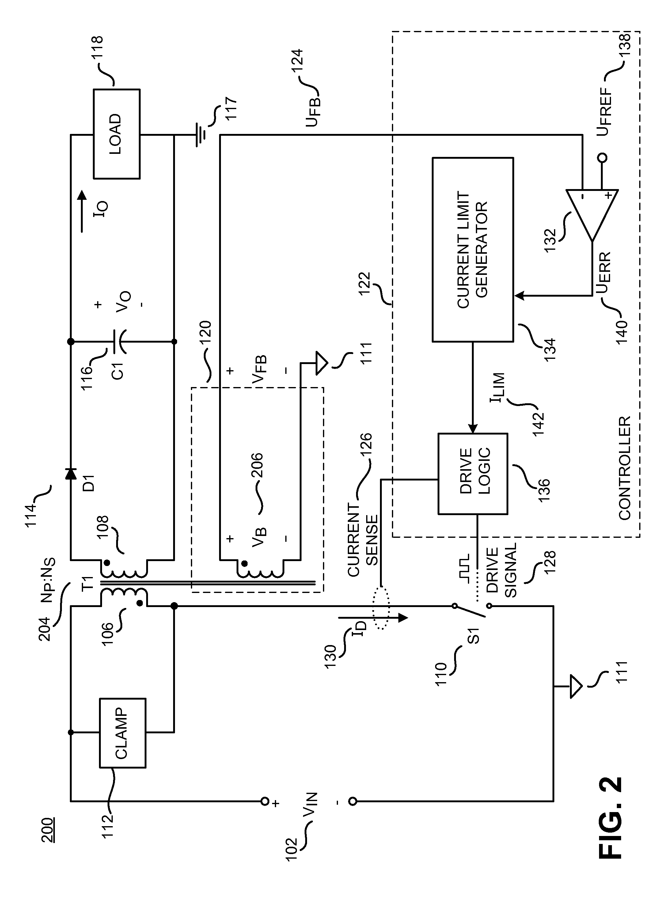
The present patent is about a type of power converter called a switched mode power converter. These converters are commonly used because they are efficient, small, and lightweight. The patent describes the use of current mode control in these converters and how the controller can regulate the output to a desired quantity by sensing and controlling various parameters such as duty ratio, switching frequency, or the number of pulses per unit time of the switch. The patent also describes the use of a winding on a coupled inductor to sense the output voltage and the use of pulse width modulation (PWM) current programmed control in the DCM mode of operation. The patent also includes a circuit diagram of an example current limit generator and a process for generating a temperature independent current limit. Overall, the patent provides technical details and methods for regulating the output of switched mode power converters using current mode control and PWM current programmed control.

Problems solved by technology

In general, a higher current limit results in a longer on-time of the switch and a larger duty ratio.

Method used


Image

  • Controller with constant current limit
  • Controller with constant current limit
  • Controller with constant current limit

Examples


Embodiment Construction

[0016]In the following description, numerous specific details are set forth in order to provide a thorough understanding of the present invention. It will be apparent, however, to one having ordinary skill in the art that the specific detail need not be employed to practice the present invention. In other instances, well-known materials or methods have not been described in detail in order to avoid obscuring the present invention.

[0017]Reference throughout this specification to “one embodiment,”“an embodiment,”“one example,” or “an example” means that a particular feature, structure or characteristic described in connection with the embodiment or example is included in at least one embodiment of the present invention. Thus, appearances of the phrases “in one embodiment,”“in an embodiment,”“one example,” or “an example” in various places throughout this specification are not necessarily all referring to the same embodiment or example. Furthermore, the particular features, structures,...


PUM


Abstract

Methods and apparatuses are disclosed for generating a temperature independent current limit. The value of the temperature independent current limit may be determined based in part on an error signal representative of a difference between an actual output value and a desired output value of a power converter. When the error signal is below a lower threshold voltage, the temperature independent current limit may be set to a first value. When the error signal is above an upper threshold voltage, the temperature independent current limit may be set to a second, higher value. When the error signal is between the lower threshold voltage and the upper threshold voltage, the temperature independent current limit may change linearly with the error signal. The error signal may be adjusted to compensate for changes in the system caused by a change in temperature.

Description

CROSS-REFERENCE TO RELATED APPLICATIONS[0001]This application is related to U.S. patent application Ser. No. ______ entitle(“Adaptive Biasing” (Attorney Docket No 68660-2000400), filed herewith,BACKGROUND[0002]1. Field[0003]The present disclosure relates generally to switched mode power converters and, more specifically, the present disclosure relates to switched mode power converters utilizing current mode control.[0004]2. Related Art[0005]Electronic devices use power to operate. Switched mode power converters are commonly used due to their high efficiency, small size, and low weight to power many of today's electronics. Conventional wall sockets provide a high voltage alternating current (ac) power. In a switched mode power converter, a high voltage ac input is converted to provide a regulated direct current (dc) output through an energy transfer element. In operation, a switch is utilized to provide the desired output by varying the duty ratio (typically the ratio of the on-time ...

Claims


Application Information

Patent Timeline
Patent Type & Authority Applications(United States)
IPC IPC(8): H02M3/335H03L5/00
CPCH02M3/33507
Inventor GAKNOKI, YURYMAO, MINGMINGZHANG, MICHAEL Y.
Owner POWER INTEGRATIONS INC
Learn More