Systems and methods utilizing randomized clock rates to reduce systematic time-stamp granularity errors in network packet communications

a time-stamp granularity and network packet technology, applied in the field of time-stamp granularity errors in network packet communications, can solve the problems of not being addressed, randomly distributed, introducing significant, and affecting the accuracy and precision of slaves,

Active Publication Date: 2013-03-28
KEYSIGHT TECH SINGAPORE (SALES) PTE LTD
View PDF9 Cites 30 Cited by
  • Summary
  • Abstract
  • Description
  • Claims
  • Application Information

AI Technical Summary

Benefits of technology

[0040]FIG. 7A is a block diagram of an embodiment for using a spread spectrum technique for randomization of time-stamp counter effective values.
[0041]FIG. 7B is a block diagram of an alternate embodiment for using a spread spectrum technique for randomization of time-stamp counter effective values.
[0042]FIG. 8 is a block diagram of an embodiment for using an increment modulation technique for randomization of time-stamp counter effective values.

Problems solved by technology

While frequency alignment within conventional TDM networks is relatively straightforward, packet-switched networks, such as networks based on Internet Protocols (“IP”), present time and frequency alignment challenges because packet networks are not conventionally designed to provide precise delivery time for data or precise timing.
In particular, packet networks typically involve multiple nodes that may store and forward data packets, potentially introducing significant, randomly distributed, transit delay variation between any two points.
There are several phenomena that interfere with the accuracy and precision whereby the slave clock can determine its time offset-from-master.
Further, because the oscillator in the slave clock is not ideal, it could drift between packet transmissions, and the assumption that the slave time clock offset-from-master (ε) is “constant” over the interval of packet exchange is not exact.
One other source of error that has not been addressed previously is the error in the time-stamp value itself.
As described below with respect to FIG. 3A (Prior Art) and FIG. 3B (Prior Art), prior methods for generating time-stamps can introduce a time-stamp error that is static and, therefore, cannot be filtered out by traditional means.
In boundary clock scenarios, this source of error is one of the primary contributors to the error in typical time transfer systems.
However, this misalignment is static in nature.
Such a systematic granularity error is impossible to filter out in subsequent processing.
Such a low-frequency error is hard to filter out, for example, using a low-pass filter.
However, this situation will likely occur only during start-up and reset of the Slave / Master devices.
Prior systems and techniques do not provide the ability to handle these cases where small systematic granularity errors exist with respect to Master and Slave time-stamp clocks that are operating at the same nominal rate, such as the MII (media independent interface) clock rate (e.g., 125 MHz) for Gigabit / sec Ethernet communications.

Method used


Image

  • Systems and methods utilizing randomized clock rates to reduce systematic time-stamp granularity errors in network packet communications
  • Systems and methods utilizing randomized clock rates to reduce systematic time-stamp granularity errors in network packet communications
  • Systems and methods utilizing randomized clock rates to reduce systematic time-stamp granularity errors in network packet communications

Examples


embodiment 400

[0049]FIG. 4 is a block diagram of an embodiment 400 for a system utilizing randomized time-of-arrival time-stamp clocks, as described herein, that have clock rates for slave time-stamp clocks that are intentionally different from the clock rates for the master time-stamp clocks. For convenience, the master-to-slave direction is considered with respect to FIG. 4, as the reverse from slave-to-master would be similar. As depicted, the Master time-stamp clock 404 has a master clock rate (fM), and the Slave time-stamp clock 414 has a slave clock rate (fS) that is intentionally different from the Master time-stamp clock rate (fS≠fM). This randomizing of clock rates allows for systematic granularity errors to be reduced or eliminated with downstream filtering techniques, such as low-pass filters in clock recovery loops.

[0050]It is again noted that the master device is the sender device sending or transmitting the initial timing packets, and the slave device is the receive device receiving...

embodiment 500

[0061]FIG. 5 is a block diagram of an embodiment 500 implementing a solution where the ratio of the time-stamp clock frequencies (fS / fM) is a rational number represented by R / T. As depicted, slave time-stamp clock 414 has a slave clock frequency (fS) that is related to the master clock frequency (fM) of the master time-stamp clock 404 by a non-integer number. As such, the ratio of the time-stamp clock frequencies (fS / fM) is a rational number. This relation can be represented by the following equation:

(fS / fM)=(TM / TS)=R / T  (Eq. 8)

where R / T is preferably a rational number (i.e., R and T are integers), and where T is preferably a large number.

[0062]As one implementation, the slave time-stamp clock rate (fS) can be selected to be slightly offset from the master time-stamp clock rate (fM). For example, with respect to a master time-stamp clock rate of 125 MHz, as describe above for Gigabit / sec Ethernet communications, a slave time-stamp clock rate of 124 MHz would be an advantageous rate ...

embodiment 600

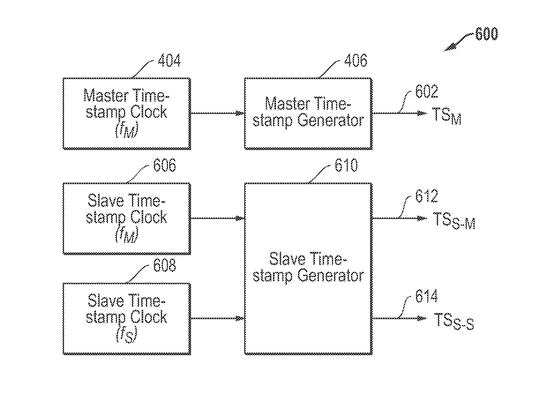
[0066]FIG. 6 is a block diagram of an embodiment 600 for a implementation where two time-stamps are used to detect a systematic granularity error. As depicted, a master time-stamp clock (fM) 404 is provided to a master time-stamp generator 406 to produce a master time-stamp (TSM) 602. As described herein, a slave time-stamp (TSS-S) 614 is generated by slave time-stamp generator 610 using a randomized slave time-stamp clock 608 operating at a rate (fS) that is different from the rate (fM) of the master time-stamp clock 404. In addition, a slave time-stamp (TSS-M) is also generated by the slave time-stamp generator 610 using a standard slave time-stamp clock 606 operating at a rate (fM) implying that is the same rate, and possibly syntonized, with the master time-stamp clock 402.

[0067]By taking time-stamps using both a standard syntonized slave time-stamp clock 606 and a randomized slave time-stamp clock 608 at the same time, a determination can be made of the existence and magnitude ...


PUM


Abstract

Systems and methods are disclosed for utilizing slave (receive) time-stamp clock rates that are different from master (sender) time-stamp clock rates to randomize and thereby reduce systematic time-stamp granularity errors in the communication of network packets. The slave (receive) time-stamp clock rate for some embodiments is set to be a fixed value that has a relationship with the master (sender) time-stamp clock rate such that the ratio of the slave (receive) clock rate to the master (sender) clock rate is a rational number. Other embodiments use a time-varying frequency for the slave (receive) time-stamp clock rate to randomize the slave (receive) time-stamp clock with respect to the master (sender) time-stamp clock. Additional time-stamps can also be generated using a slave (receive) time-stamp clock having a rate set to equal the rate of the master (sender) time-stamp clock signal. Further spread spectrum and/or delta-sigma modulation techniques can be applied to effectively randomize the slave (receive) time-stamp clock.

Description

RELATED APPLICATIONS[0001]This application claims priority to the following co-pending provisional application: U.S. Provisional Patent Application Ser. No. 61 / 539,806, filed Sep. 27, 2011, and entitled “SYSTEMS AND METHODS UTILIZING RANDOMIZED SLAVE TIME-STAMP CLOCK RATES TO REDUCE SYSTEMATIC TIME-STAMP GRANULARITY ERRORS IN NETWORK PACKET COMMUNICATIONS,” which is hereby incorporated by reference in its entirety.TECHNICAL FIELD OF THE INVENTION[0002]This invention relates to the use of time-stamps in network packet communications and, more particularly, to time-stamp granularity errors in network communications.BACKGROUND[0003]One of the more important requirements of a digital communication network is to support real-time communications applications which, typically, require time or frequency alignment, or a combination of both. For example, time alignment is used by real-time instrumentation systems gathering data at specific time intervals or operating machinery according to sp...

Claims


Application Information

Patent Timeline
Patent Type & Authority Applications(United States)
IPC IPC(8): H04L7/00
CPCH04J3/0667H04J3/0697H03L7/1974H04J3/0661H03L7/16
Inventor WEBB, III, CHARLES A.SHENOI, KISHAN
Owner KEYSIGHT TECH SINGAPORE (SALES) PTE LTD
Why Eureka
Try Eureka