
Cryogenic cooling system with wicking structure

Active Publication Date: 2013-03-28
GENERAL ELECTRIC CO
View PDF16 Cites 2 Cited by
  • Summary
  • Abstract
  • Description
  • Claims
  • Application Information

AI Technical Summary

Benefits of technology

The patent describes a solution to reduce the amount of coolant required in a cryogenic system by using a wicking structure that is in thermal contact with a component to be cooled. This provides a local cooling structure around the components, which means that only a small amount of liquid helium is required at the exact location where heat enters the system. This solution improves temperature uniformity, cryostability of individual components, and enhances the quench stability margin of superconducting magnets. In simple terms, this technology allows for more efficient cooling and reduced coolant usage in cryogenic systems.

Problems solved by technology

Cryogenic cooling system employed for cooling the imaging device components utilize abundant amount of the cryogenic fluid to provide localized cooling, thereby increasing the cost and also the complexity of the system.
Unfortunately, cryogenic systems, such as MRI systems, utilize large amounts of coolant, for example, about 1000 to 2000 liters of Helium, to provide localized cooling to the superconducting coils and cryogenic vessel walls.
The coolant required in conventional cryogenic systems is very costly.
In addition, even though the cryogenic vessel containing the superconducting magnet uses superior insulation, a small amount of heat from the outside will conduct into the cryogenic vessel causing additional liquid helium boiloff.
During this transportation process, typically a significant greater amount of liquid helium is lost.
Due to availability and scarcity of high purity liquid helium at different locations in the world this might be very costly.

Method used


Image

  • Cryogenic cooling system with wicking structure
  • Cryogenic cooling system with wicking structure
  • Cryogenic cooling system with wicking structure

Examples


Embodiment Construction

[0014]While only certain features of the invention have been illustrated and described herein, many modifications and changes will occur to those skilled in the art. It is, therefore, to be understood that the appended claims are intended to cover all such modifications and changes as fall within the true spirit of the invention. In the specification and claims, reference will be made to a number of terms, which have the following meanings.

[0015]The singular forms “a”, “an” and “the” include plural referents unless the context clearly dictates otherwise. Approximating language, as used herein throughout the specification and claims, may be applied to modify any quantitative representation that could permissibly vary without resulting in a change in the basic function to which it is related. Accordingly, a value modified by a term such as “about” is not to be limited to the precise value specified. In some instances, the approximating language may correspond to the precision of an in...


PUM


Abstract

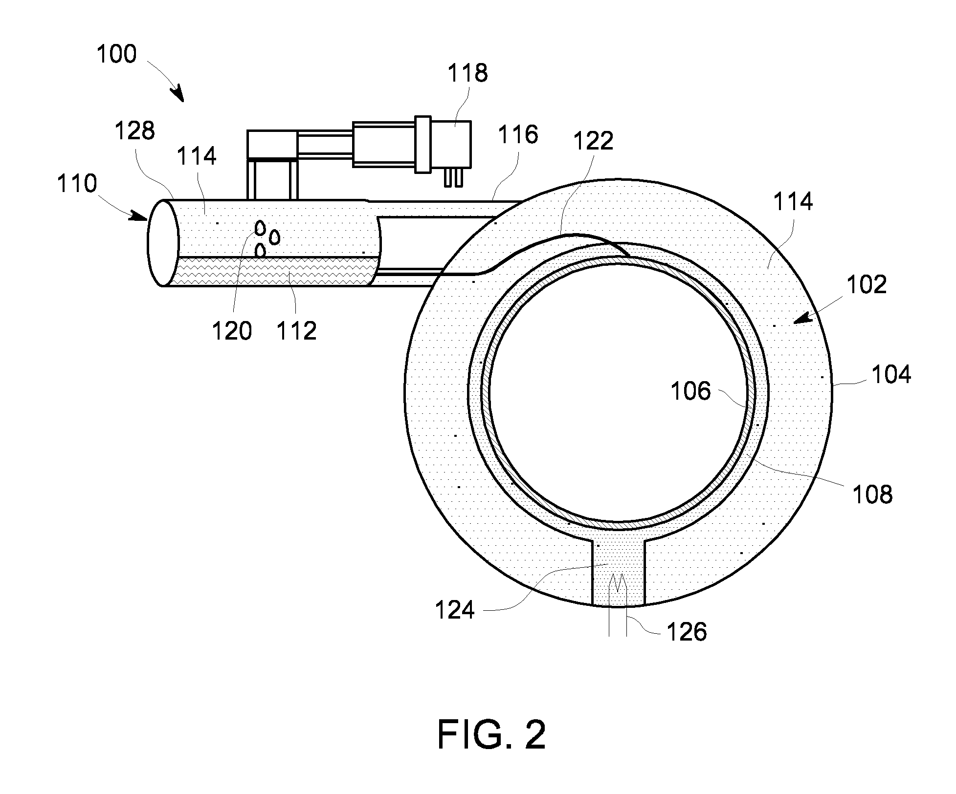
A cryogenic cooling system includes a chamber defined by an outer wall and an inner wall, the chamber housing at least one component to be cooled; a wicking structure in thermal contact with one of the outer wall and the inner wall of the chamber; and a delivery system in a spaced apart relationship with the chamber and fluidly connected to the wicking structure for transporting a working fluid to and from the wicking structure. Also provided is a magnetic resonance imaging system including the cryogenic cooling system.

Description

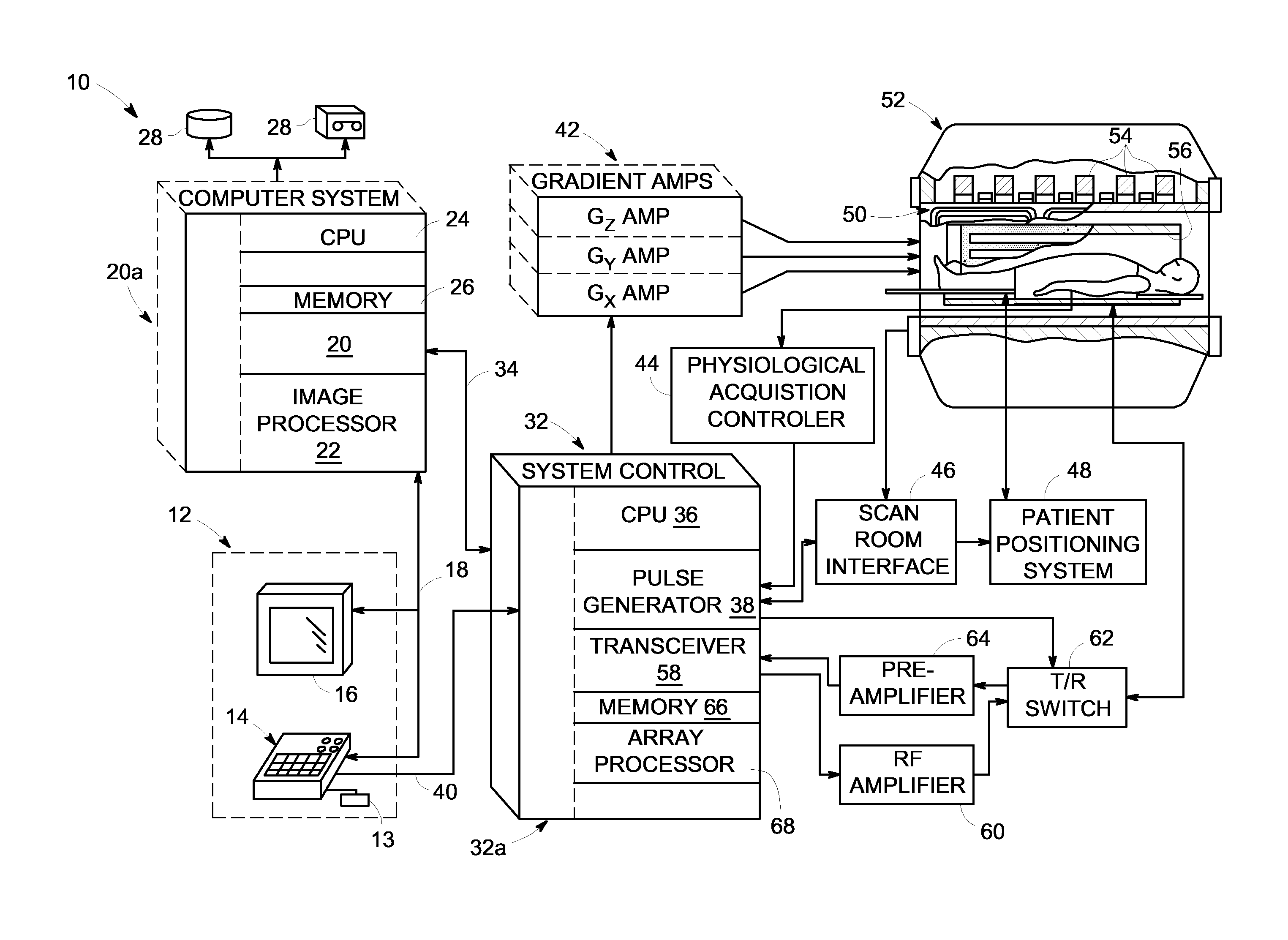
BACKGROUND[0001]The invention relates generally to a cooling system for an imaging system and, more particularly, to a wicking structure for a cryogenic cooling system in a magnetic resonance imaging (MRI) device.[0002]Imaging devices, such as magnetic resonance imaging (MRI) devices, are typically used to diagnose patients in medical environments. The generated magnetic resonance image is a map of weak magnetization originated from the atomic nuclei in the body tissue as influenced by presence of an external magnetic field. By detecting these influences, MRI devices produce detailed images of a patient's internal tissues and organs, thereby enabling diagnosis of disease, injuries, among other physiological conditions of a patient.[0003]In the traditional MRI system, the superconductive electromagnet has a number of loops of coiled wire that are bathed in a cryogenic fluid, such as liquid helium. This cryogenic fluid cools the coiled wire to extremely low temperatures, maintaining t...

Claims


Application Information

Patent Timeline
IPC IPC(8): G01R33/035F28D15/04G01R33/34
CPCG01R33/3815H01F6/04F25B2500/09F25B9/14G01R33/3804F25B9/00
Inventor DE BOCK, HENDRIK PIETER JACOBUSZIA, JALAL HUNAINSTAUTNER, ERNST WOLFGANGDENG, TAOJIANG, LONGZHIEINZIGER, WILLIAM LOUISSHANG, WENLVOVSKY, YURIAMM, KATHLEEN MELANIECITVER, GREGORYZHANG, TAO
Owner GENERAL ELECTRIC CO
Features
  • Generate Ideas
  • Intellectual Property
  • Life Sciences
  • Materials
  • Tech Scout
  • Unparalleled Data Quality
  • Higher Quality Content
  • 60% Fewer Hallucinations
Learn More