
Passive microcoolant loop for an electrochemical fuel cell

a fuel cell and microcoolant technology, applied in the field of electrochemical fuel cells, can solve the problems of local heating within the stack that could adversely affect the stack, and achieve the effect of reducing the amount of coolant and reducing the percentage of coolant recirculation in the coolant loop

Active Publication Date: 2006-06-22
BALLARD POWER SYSTEMS
View PDF7 Cites 5 Cited by
  • Summary
  • Abstract
  • Description
  • Claims
  • Application Information

AI Technical Summary

Benefits of technology

[0014] During start-up, the stack valve is closed such that the electrochemical fuel cell stack is fluidly isolated from the standard coolant loop. Coolant in the standard coolant loop circulates through the driving gear pump head of the startup coolant loop by way of the drive loop. The driving gear pump head, in turn, drives the driven gear pump head. As there is no additional motor required to power the driving gear pump head, the startup coolant loop can also be described as a passive coolant loop. The driven gear pump head recirculates coolant in the fuel cell stack and helps to quickly bring the temperature of the stack to the desired temperature. If coolant did not flow through the stack, localized heating within the stack could detrimentally affect the stack. By minimizing the coolant volume in the startup loop, and in particular, by having a smaller coolant volume than in the standard coolant loop, more efficient heating can occur. In this manner, the start up coolant loop can also be described as a passive microcoolant loop.
[0016] In an embodiment, coolant from the standard coolant loop mixes with the coolant in the startup loop when the stack valve opens. This opening of the stack valve reduces the amount of coolant from the standard coolant loop available for driving the driving gear pump head; thus the percentage of coolant recirculation in the coolant loop is reduced. Once the operating temperature of the fuel cell stack is reached, the stack valve is fully opened and provides a minimal pressure drop. With the valve fully open, the pressure of the coolant in the standard coolant loop on the driving gear pump head is essentially equal to and counteracts the pressure exerted on the driven gear pump head; thus, the driving and driven gear pump heads stop rotating and recirculation in the startup coolant loop ceases.

Problems solved by technology

If coolant did not flow through the stack, localized heating within the stack could detrimentally affect the stack.

Method used


Image

  • Passive microcoolant loop for an electrochemical fuel cell
  • Passive microcoolant loop for an electrochemical fuel cell
  • Passive microcoolant loop for an electrochemical fuel cell

Examples


Embodiment Construction

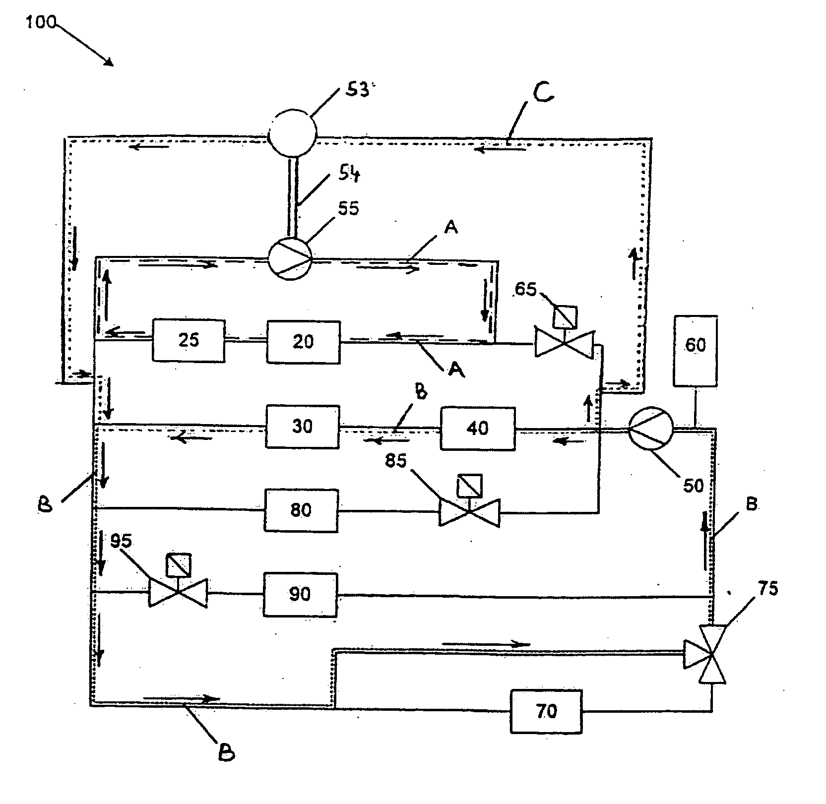
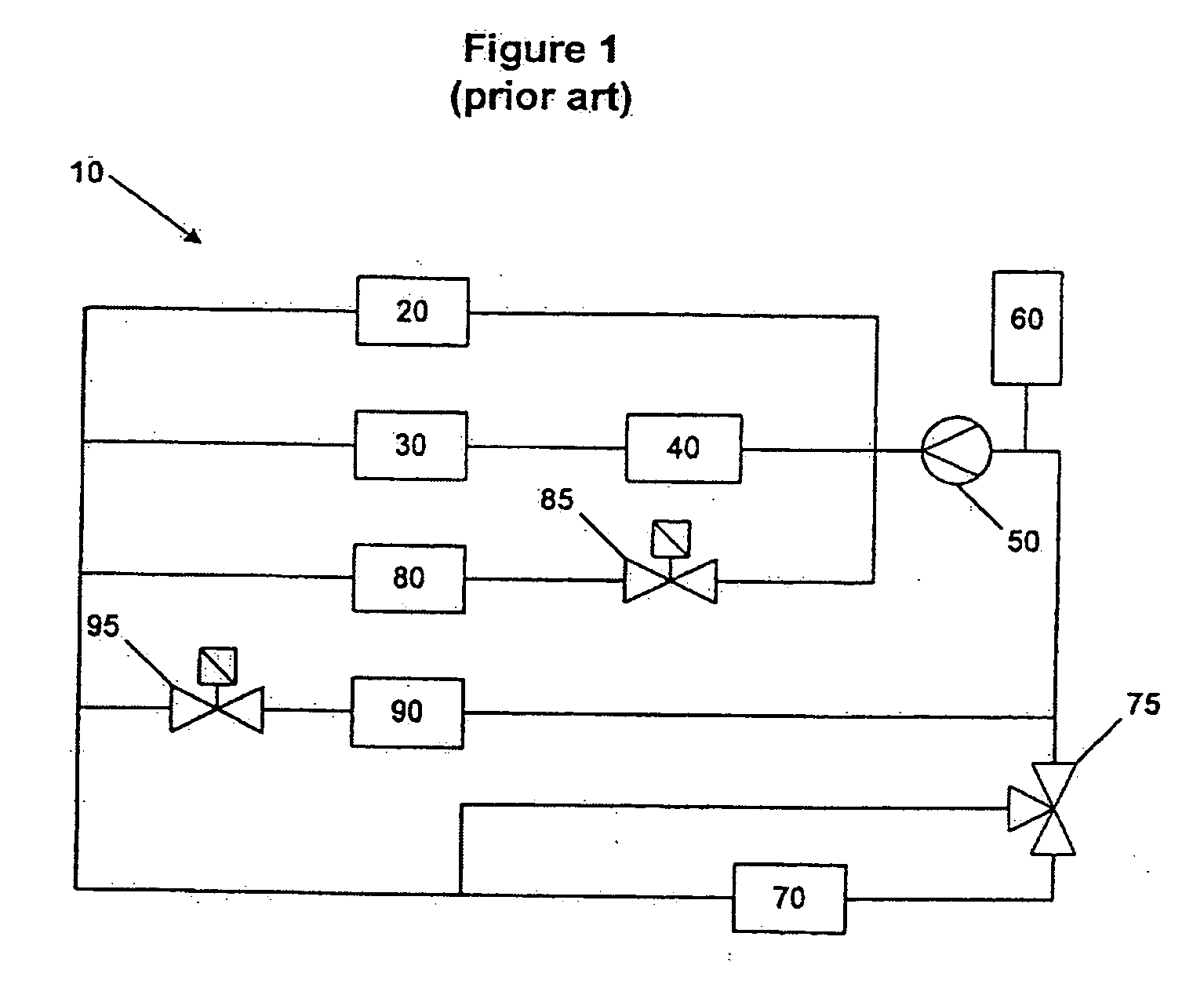
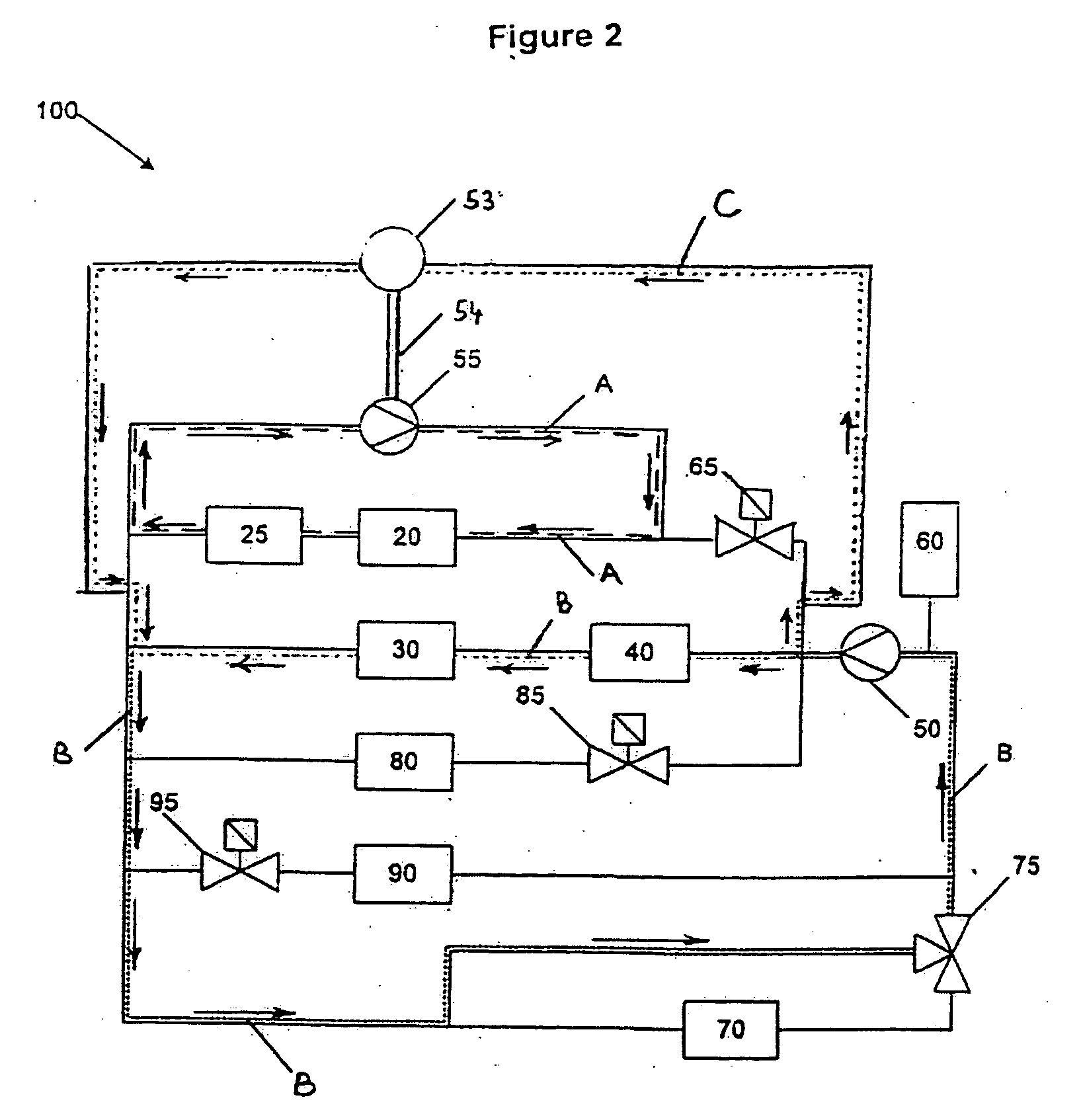
[0023]FIG. 1 is a schematic of a conventional prior art electrochemical fuel cell system coolant subsystem 10. Electrochemical fuel cell system coolant subsystem 10 may comprise a pump 50 fluidly connected to a fuel cell stack 20, a compressor 30, a cathode feed heat exchanger 40 and a coolant reservoir 60. Coolant from coolant reservoir 60 can then be circulated through fuel cell stack 20, compressor 30 and cathode feed heat exchanger 40 to assist with temperature regulation of these components. In particular, with respect to compressor 30, temperature regulation of the compressor motor and the compressor inverter (not shown) may be desired, either individually or together. Temperature sensors (not shown) may measure the temperature of fuel cell stack 20 and / or the temperature of the coolant circulating through electrochemical fuel cell system coolant subsystem 10. The electrochemical fuel cell system coolant subsystem 10 may also comprise a radiator 70 and a radiator valve 75. Onc...


PUM

PropertyMeasurementUnit
temperatureaaaaaaaaaa

Abstract

Improvements in freezing and sub-freezing startup time for an electrochemical fuel cell system may be observed by having a passive coolant microloop using two gear pump heads. During a cold start, a stack valve is initially fully closed and causes all system coolant arriving at the module to run through a driving gear pump head. This causes a driven gear pump head to recirculate coolant inside the module. In an embodiment, the stack valve is a thermostatic valve that begins to open as the coolant begins to warm up. This allows a small bleed of system coolant into the module and decreases the percentage of microloop recirculation. When operating temperature is reached, the thermostatic valve is fully open and system coolant inlet pressure on the driving gear pump head counteracts the pressure on the driven gear pump head, thus stopping recirculation.

Description

BACKGROUND OF THE INVENTION [0001] 1. Field of the Invention [0002] The present invention relates to electrochemical fuel cells and more particularly to subsystems and methods for controlling the temperature of a fuel cell system during startup. [0003] 2. Description of the Related Art [0004] Electrochemical fuel cells convert reactants, namely fuel and oxidant fluid streams, to generate electric power and reaction products. Electrochemical fuel cells employ an electrolyte disposed between two electrodes, namely a cathode and an anode. The electrodes each comprise an electrocatalyst disposed at the interface between the electrolyte and the electrodes to induce the desired electrochemical reactions. The location of the electrocatalyst generally defines the electrochemically active area. [0005] Polymer electrolyte membrane (PEM) fuel cells generally employ a membrane electrode assembly (MEA) consisting of an ion-exchange membrane disposed between two electrode layers comprising porous...

Claims


Application Information

Patent Timeline
Patent Type & Authority Applications(United States)
IPC IPC(8): H01M8/04
CPCH01M2250/20Y02T90/32H01M8/04007H01M8/04253H01M8/04268Y02E60/50Y02T90/40H01M8/04
Inventor GALLAGHER, EMERSON R.
Owner BALLARD POWER SYSTEMS
Features
  • Generate Ideas
  • Intellectual Property
  • Life Sciences
  • Materials
  • Tech Scout
  • Unparalleled Data Quality
  • Higher Quality Content
  • 60% Fewer Hallucinations
Learn More