Power generation unit, electronic apparatus, transportation device, and method of controlling power generation unit
- Summary
- Abstract
- Description
- Claims
- Application Information
AI Technical Summary
Benefits of technology
Problems solved by technology
Method used
Image

Examples
first embodiment
A. First Embodiment
A-1. Structure of Power Generation Unit
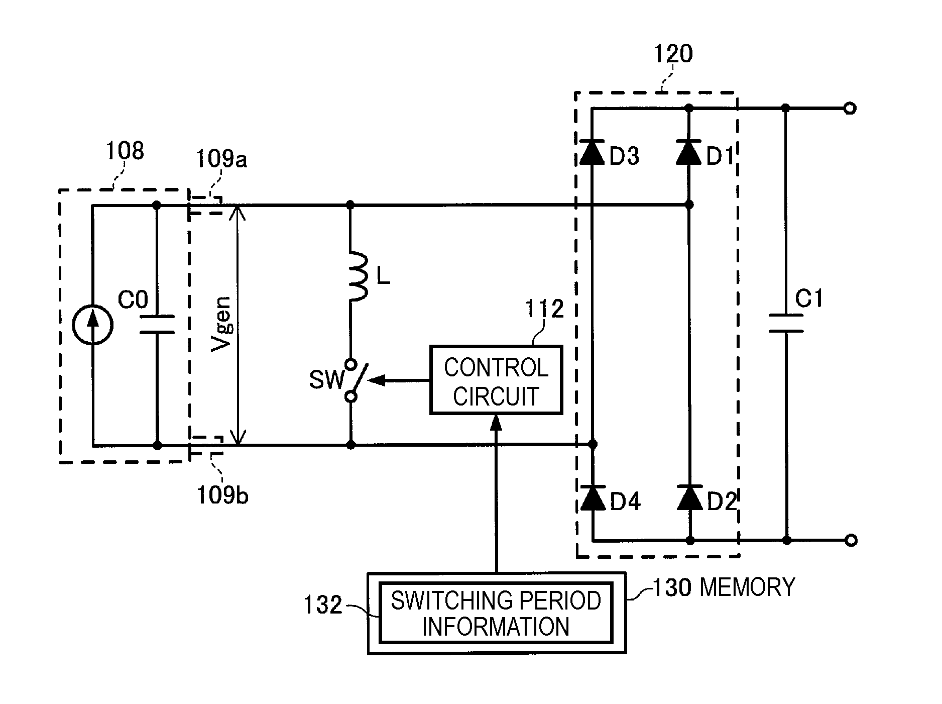
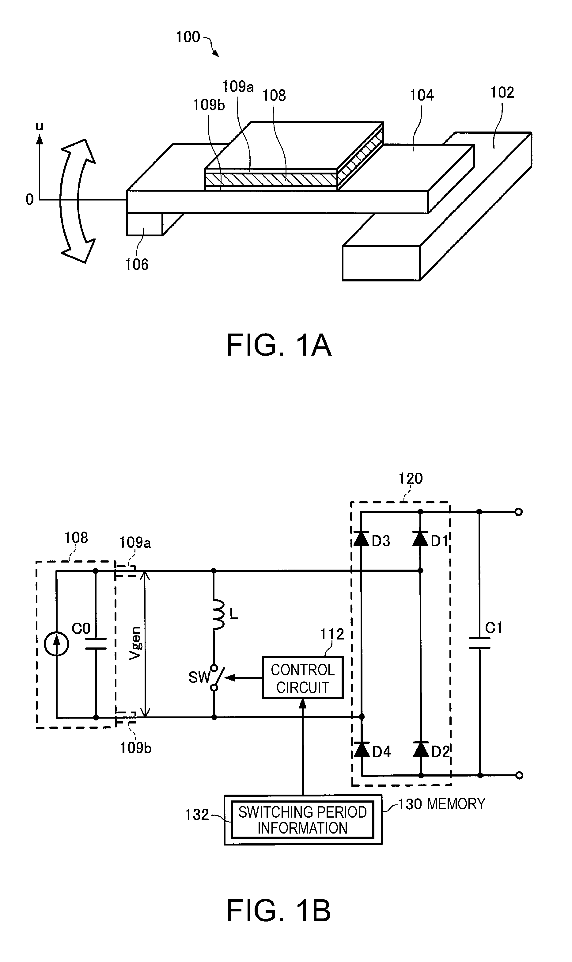
[0081]FIGS. 1A and 1B are explanatory diagrams showing a structure of a power generation unit 100 according to the present embodiment. FIG. 1A shows a mechanical structure of the power generation unit 100, and FIG. 1B shows an electrical structure thereof. The mechanical structure of the power generation unit 100 according to the present embodiment is formed as a cantilever structure in which a beam 104 having a mass 106 disposed at the tip thereof is fixed to a base 102 on the base end side thereof, and the base 102 is preferably fixed inside the power generation unit 100. Further, on the surface of the beam 104 there is attached a piezoelectric element 108 formed of a piezoelectric material such as lead zirconium titanate (PZT), and on the surfaces of the piezoelectric element 108 there are disposed a first electrode (an upper electrode) 109a and a second electrode (a lower electrode) 109b each formed of a metal thin film r...
second embodiment
B. Second Embodiment
[0127]In the power generation unit 100 according to the first embodiment, since the switch SW is set to the ON state at an arbitrary timing (with an arbitrary phase difference) independently of the state of the vibration of the beam 104, the power generation efficiency is varied dramatically due to the timing at which the switch SW is set to the ON state. Therefore, in the power generation unit 100 according to the second embodiment, the state of the vibration of the beam 104 is detected at a predetermined timing, and an adjustment is performed so that the switch SW is set to the ON state at the timing at which the deformation direction of the beam 104 is switched to thereby further improve the power generation efficiency. It should be noted that since some of the electrical power thus generated is consumed for detecting the state of the vibration of the beam 104, in particular in the power generation unit according to the second embodiment, in order to reduce th...
third embodiment
C. Third Embodiment
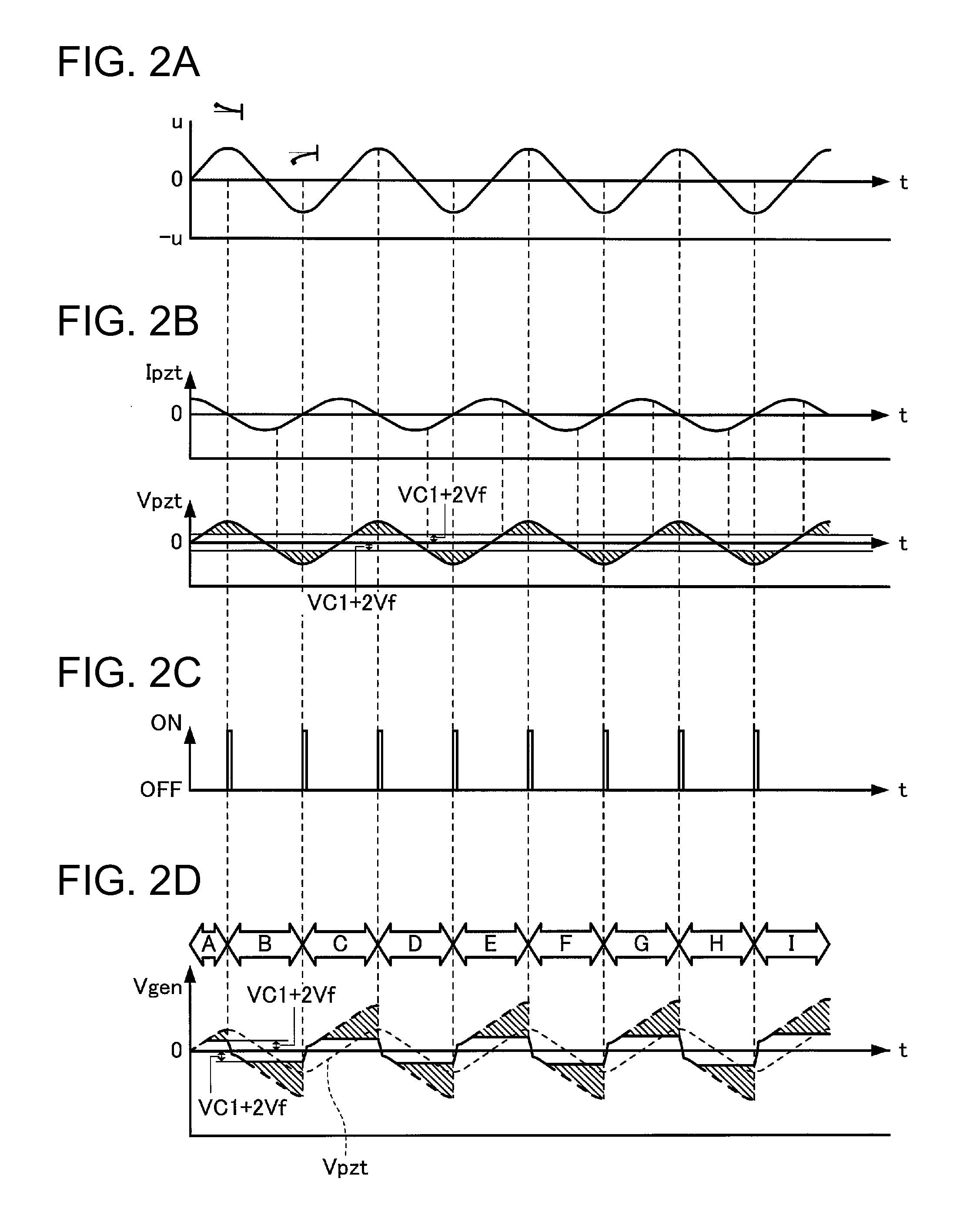
[0153]Although in the power generation unit 100 according to the second embodiment, the current flowing through the full bridge rectifier 120 is detected to thereby determine the timing at which the deformation direction of the beam 104 is switched, since the current flowing through the full bridge rectifier 120 is so minute that the exact determination is difficult in some cases. Further, since the voltage Vgen between the terminals of the piezoelectric element 108 is clipped at the voltage of the sum of VC1 and 2Vf as described above, it is unachievable to detect the peak of the voltage Vgen. Therefore, in the power generation unit 100 according to the third embodiment, a second piezoelectric element is provided to the beam 104, and the peak of the voltage generated in the second piezoelectric element is detected to thereby perform the ON / OFF control of the switch SW.
[0154]FIGS. 17A and 17B are explanatory diagrams showing a structure of the power generation uni...
PUM
 Abstract
Description
Claims
Application Information
 - R&D
- Intellectual Property
- Life Sciences
- Materials
- Tech Scout
- Unparalleled Data Quality
- Higher Quality Content
- 60% Fewer Hallucinations
Browse by: Latest US Patents, China's latest patents, Technical Efficacy Thesaurus, Application Domain, Technology Topic, Popular Technical Reports.
© 2025 PatSnap. All rights reserved.Legal|Privacy policy|Modern Slavery Act Transparency Statement|Sitemap|About US| Contact US: help@patsnap.com