Method and system of ozone generation

a technology of ozone generation and ozone gas, which is applied in the field of ozone gas generation, can solve the problems of not widespread application of ozone in the food industry, oxygen, air from which ozone gas is generated, and also contains nitrogen and water vapor, so as to increase the amount of generated ozone, increase the reliability of the device, and the effect of high voltage impulses

Active Publication Date: 2019-07-18
DM ECO PLASMA INC
View PDF0 Cites 2 Cited by
  • Summary
  • Abstract
  • Description
  • Claims
  • Application Information

AI Technical Summary

Benefits of technology

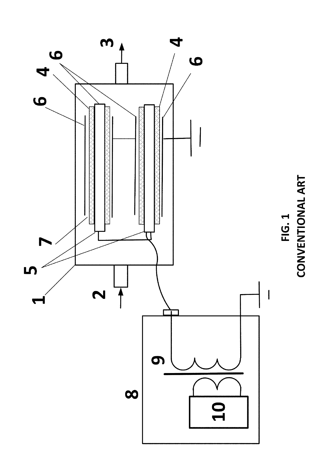
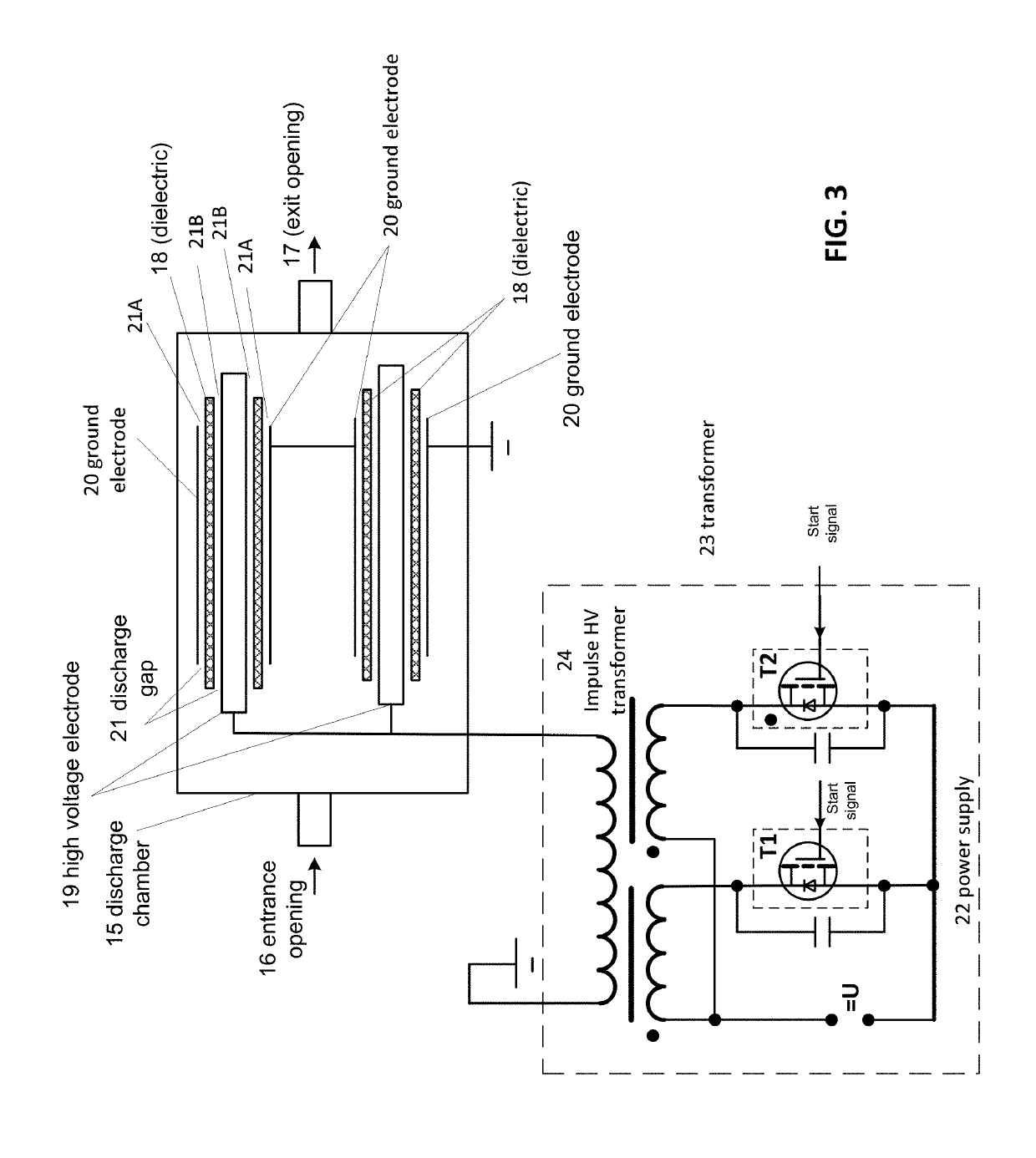
[0028]In one aspect, there is a provided a device for generation of ozone in the impulse barrier discharge that includes the discharge chamber with entrance and exit openings with high voltage electrodes grounded and covered by dielectric material inside of it. The power supply connected to the electrodes and generating high voltage impulses is located outside of the chamber. The discharge chamber is different from described prototype used for non-dried atmospheric air. In this case discharge gap can be divided on two parts between high voltage electrode and dielectric and between dielectric and grounded electrode. In both gap parts ignites the impulse barrier discharge with. The applied voltage should have rate of increase of voltage in a region 5 kV / μs and up to 50 kV / μs. Voltage pulses can be positive, negative or bipolar, rather than asymmetric impulses with maximum amplitude of the negative part of the impulse is at a minimum twice higher than the positive part of the impulse used in prototype. Ozone generator supplied by the dry air or oxygen or non-dried air through the entrance opening which then goes through discharge gaps between high voltage and ground electrodes rather then only non-dried air like prototype. The technical result of the invention is considerable increase in reliability of the device, an increase in the amount of generated ozone, lowering of specific energy expenditures, and elimination of air preparation in the case of using non-dried air.
[0029]An approach used for generation of ozone from non-dried atmospheric air can be used also for generation of ozone from dry air or oxygen. As with regular DBD ozone generators, deep drying the ozone generator's discharge chamber is needed. Ideally, an ozone generator can start operation only when dew point inside discharge chamber will reach −70° C. This process needs several hours, or sometimes a few days, but only in this case regular DBD ozone generator can work stably for a long time. Use of PDBD ozone generator, which can operate without any drying of air or oxygen, can solve this problem.

Problems solved by technology

Ozonation is green technology because ozone has limited lifetime and automatically decompose after decontamination process.
Despite the evident advantages of ozone technology, application of ozone in food industry is not widespread, because of significant operation problems of ozone generating equipment.
In the case of utilization of regular air ozone generator, the problem is that the air from which the ozone is generated, along with the oxygen, also contains nitrogen and water vapor.
The nitric acid quickly forms a conductive film on the surface of the dielectric barrier discharge (DBD) ozone generator electrodes, which results in failure of the generator's normal operation.
Oxygen ozone generators have the same problems because the rest of nitrogen and water vapors exist in oxygen as admixtures.
This problem is the reason why, in order to operate regular ozone generators, deep drying of working gas is needed in the ozone generator's discharge chamber.
Such operation requirements are usually unacceptable for operation on a real plant, and ozone generators usually start operations before reaching such a low dew point.

Method used


Image

  • Method and system of ozone generation
  • Method and system of ozone generation
  • Method and system of ozone generation

Examples


example # 1

EXAMPLE #1

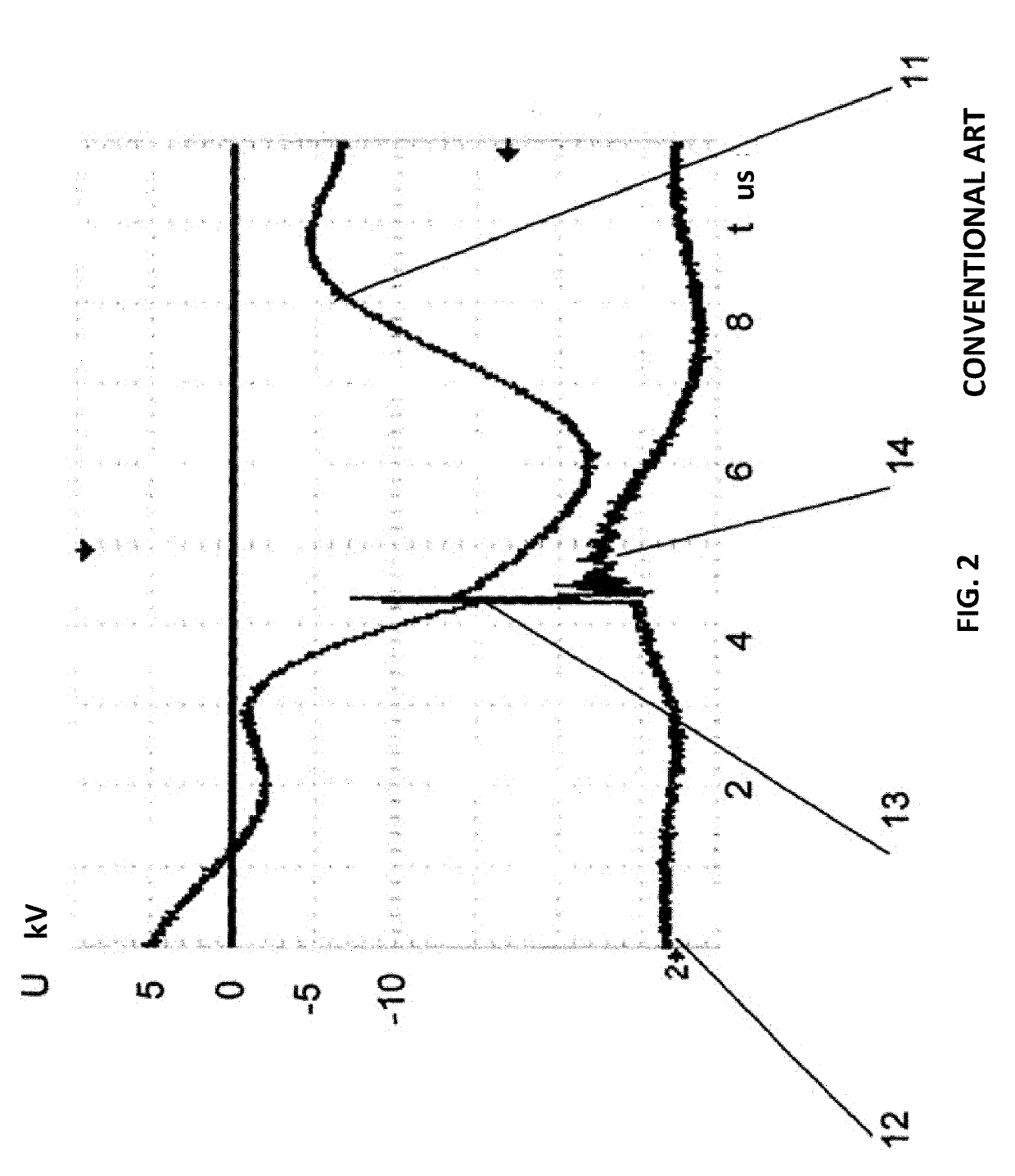
[0084]The source of high voltage impulses generates impulses with a frequency f of about 1500 Hz (generally, from about 1 KHz to about 2 KHz). The form of the impulse is illustrated in FIG. 4.

[0085]The front of increase of the first negative peak is 0.5 μs at an amplitude 5 kV. Thus, the rate of increase dU / dt of the negative peak of the impulse is 10 kV / us. Maximum amplitude of positive peaks is 8.5 kV with a rise time 0.5 μs so the rate of increase dU / dt is 17 kV / μs. The source of high voltage impulse is attached to high voltage electrodes of the cylindrical shape and diameter 12 mm inserted into the quartz pipe with inner diameter 12 mm and outer diameter 15 mm. High voltage electrodes and quartz pipe inserted to the discharge chamber with air cooling system for the outside grounded electrodes with inner diameter 17 mm. The electric gas barrier discharge ignites between the quartz pipe and grounded electrodes. The power is monitored in the experiment. A stationary tempe...

example # 2

EXAMPLE #2

[0087]The source of high voltage impulses generates impulses with a frequency f of about 1500 Hz. The shape of the impulse is also close to that illustrated in FIG. 4.

[0088]The front of increase of the first negative peak is 0.5μs at an amplitude 7 kV. Thus, the rate of increase dU / dt of the negative peak of the impulse is 14 kV / μs. The maximum amplitude of positive peaks is 10 kV with a rise time 0.5 μs so the rate of increase dU / dt is 20 kV / μs. The source of high voltage impulse is attached to high voltage electrodes of the cylindrical shape and diameter 10 mm inserted to the quartz pipe with inner diameter 12 mm and outer diameter 15 mm. The high voltage electrodes and the quartz pipe are inserted to the discharge chamber with a water cooling system for the outside grounded electrodes with inner diameter 17 mm. So, in this example, discharge gap has been divided into two parts. The electric gas barrier discharge ignites between the quartz pipe and grounded electrodes an...


PUM

PropertyMeasurementUnit
peak currentaaaaaaaaaa
voltageaaaaaaaaaa
voltageaaaaaaaaaa

Abstract

An ozone generator includes a discharge chamber; an inlet opening for feeding air into the discharge chamber; an outlet opening for removing ozone from the discharge chamber; and at least two cylindrical electrode sets in the discharge chamber. Each electrode set includes a ground electrode; a high voltage electrode; a dielectric between the ground electrode and the high voltage electrode; the dielectric separated from the ground electrode by a first discharge gap, and the dielectric separated from the high voltage electrode by a second discharge gap. A high voltage power supply provides a voltage impulse to the high voltage electrode of at least 2 kV (at least 5 kV is most cases), and a peak current of at least 1 ampere (at least 4 amperes in most cases). The high voltage power supply provides a dU/dt of the voltage impulse of between 5 kV/μsec and 50 kV/μsec.

Description

CROSS REFERENCE TO RELATED APPLICATIONS[0001]This application is a continuation in part of U.S. patent application Ser. No. 15 / 872,086, filed on Jan. 16, 2018, incorporated herein by reference in its entirety.BACKGROUND OF THE INVENTIONField of the Invention[0002]The invention relates to ozone generation using an oxygen containing gas in an impulse plasma barrier discharge.Description of the Related Art[0003]Ozonation is an extremely effective technology for decontamination of water, air rooms and food products. For example, typical energy costs for decontamination of 1 ton of water or 100 m3 of air is approximately 10 W*hours or 0.1 cent.[0004]Ozonation is green technology because ozone has limited lifetime and automatically decompose after decontamination process. Reaction products of ozone are incomparably safer then reaction products of chlorine, which are poisonous and cancerogenic. Thus, there is considerable economic and health-related motivation in replacing chlorine use in ...

Claims


Application Information

Patent Timeline
Patent Type & Authority Applications(United States)
IPC IPC(8): C01B13/10H05H1/24H05H1/34
CPCC01B13/10H05H1/2406H05H1/34H05H2001/2412H05H2001/2431C01B13/11C01B2201/22C01B2201/62C01B2201/64C01B2201/66C01B2201/72C01B2201/76H05H1/2431H05H2245/15
Inventor MEDVEDEV, DMITRY
Owner DM ECO PLASMA INC
Why Eureka
Try Eureka