
Water decomposition apparatus and water decomposition method

a technology of water decomposition apparatus and water decomposition method, which is applied in the direction of electrode coating, final product manufacturing, sustainable manufacturing/processing, etc., can solve the problems of large reduction of inability to perform stable gas generation, and decrease in gas generation efficiency of hydrogen, oxygen and the like, so as to achieve high gas generation efficiency and increase the amount of hydrogen gas generation for a long time. , the effect of stable generation

Inactive Publication Date: 2019-07-16
FUJIFILM CORP +1
View PDF4 Cites 0 Cited by
  • Summary
  • Abstract
  • Description
  • Claims
  • Application Information

AI Technical Summary

Benefits of technology

The invention provides a water decomposition apparatus and method that can maintain high gas generation efficiency even early in the light irradiation process and even after time has passed. It can recover the gas generation amount of hydrogen gas or the like and generate it stably for a long time on average. Additionally, it can increase the integrated amount of hydrogen gas generation for a long time, even if the gas generation amount has decreased over time.

Problems solved by technology

Therefore, there is a problem that the gas generation efficiency of hydrogen, oxygen, and the like decreases.
Therefore, there is a problem that the gas generation efficiency of hydrogen, oxygen, and the like is greatly decreased, and stable gas generation cannot not be performed.
However, since the amount of generated gas decreases with the elapse of time, there is a problem that the integrated amount of generation of hydrogen gas or the like for a long time is small.
However, even if shielding is performed for about 1.25 hours after irradiation is performed for about 3.75 hours and light irradiation is resumed after shielding, a decrease in the amount of the cathode current accompanying the elapse of time becomes large.
As a result, sufficient recovery is not shown even if shielding is performed after that.
As a result, there is a problem that the integrated amount of generation of hydrogen gas for a long time or the like is small.

Method used


Image

  • Water decomposition apparatus and water decomposition method
  • Water decomposition apparatus and water decomposition method
  • Water decomposition apparatus and water decomposition method

Examples


example 1

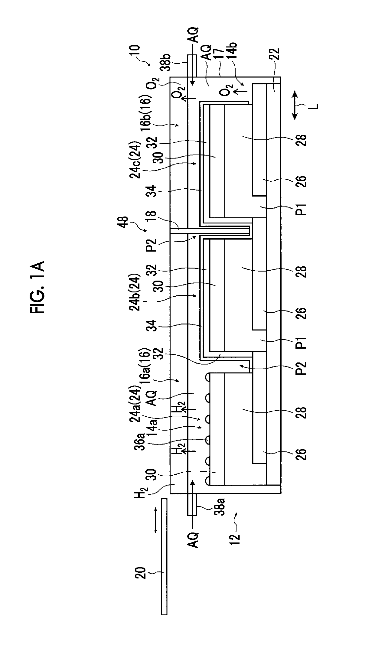
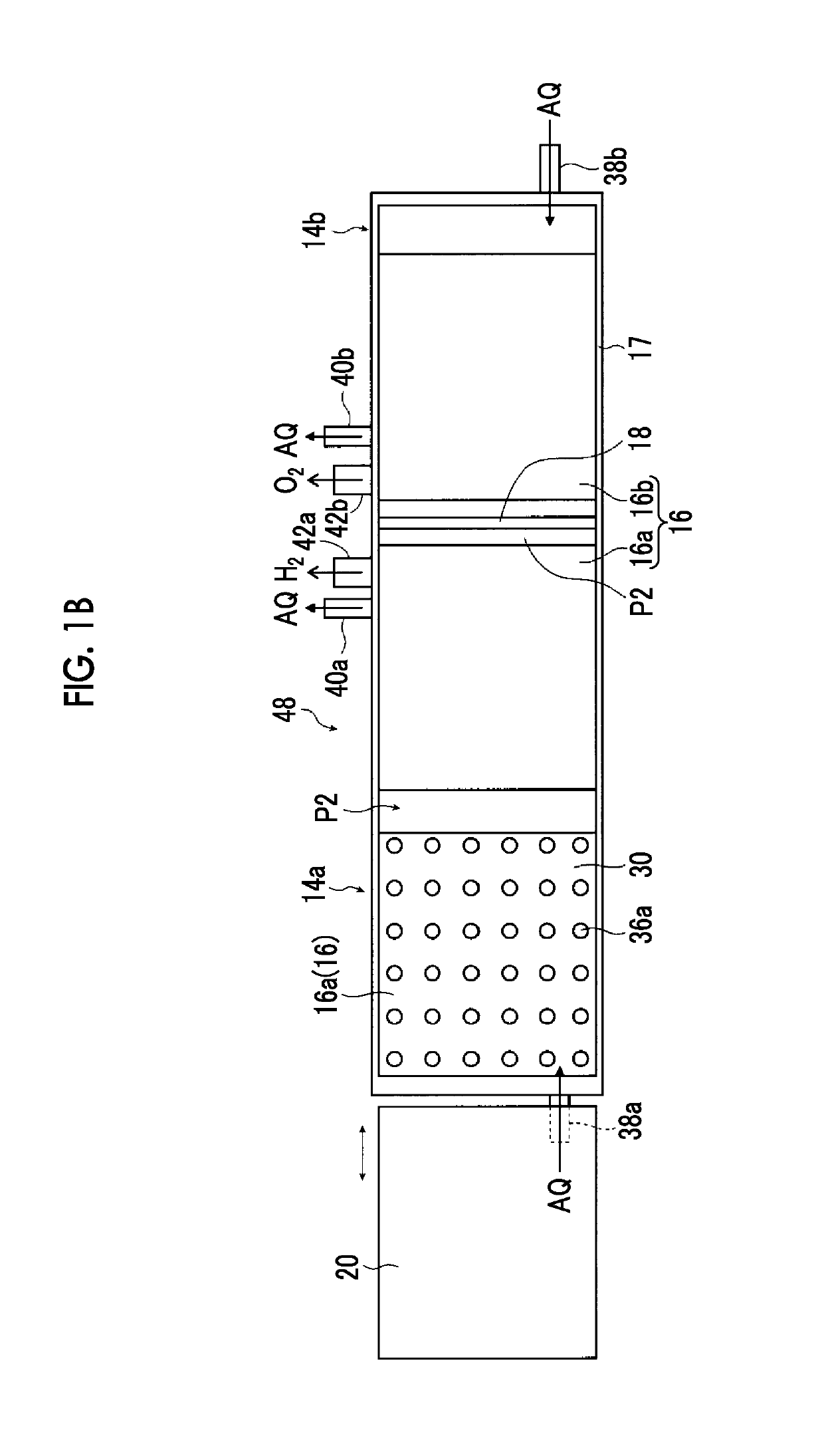
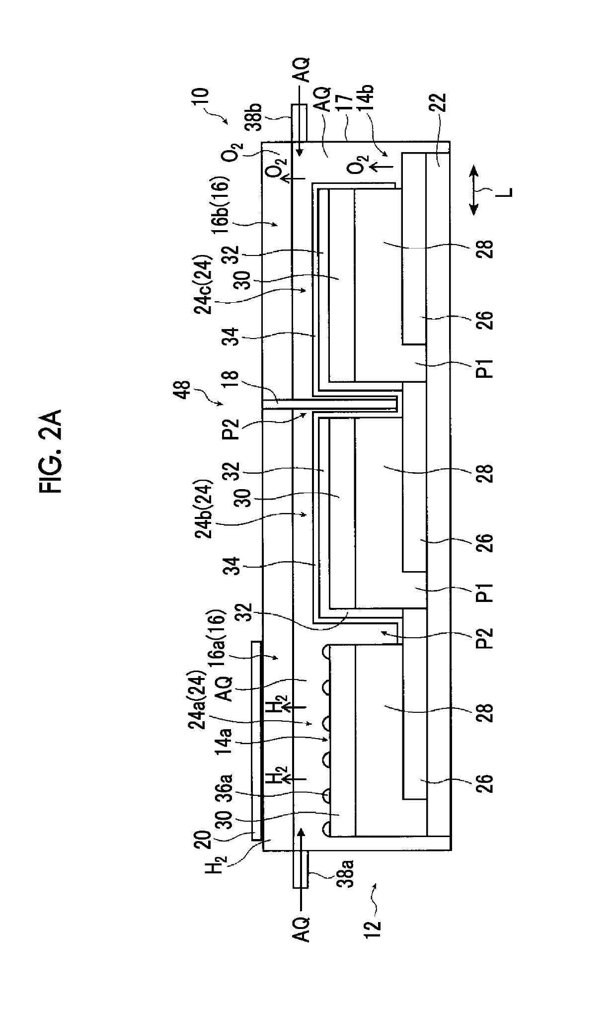
[0167]First, as Example 1, the integrated amount of generation of hydrogen gas was evaluated by repeating performing shielding for a short time after the water decomposition apparatus 10 illustrated in FIGS. 1A and 1B in which a photoelectric conversion layer was formed of a CIGS film was made, the electrolytic chamber 16 was filled with an electrolyte aqueous solution, and light irradiation was performed for a given time.

[0168]The water decomposition apparatus of Example 1 was manufactured according to a making flow illustrated in a flowchart of FIG. 6.

[0169]First, in Step S12, a soda lime glass substrate was prepared as the supporting substrate 22.

[0170]Next, in Step S14, a Mo film was formed by forming Mo as a film of about 500 nm on a soda lime glass substrate using a sputtering method, and then, in Step S16, Mo film was cut and patterned by laser scribing, gaps serving as the separation grooves P1 are formed, and as illustrated in FIG. 1A, Mo back electrodes 26 were formed.

[017...

example 2

[0180]Next, as Example 2, the integrated amount of generation of hydrogen gas was evaluated by repeating performing shielding for a short time (5 minutes) after the water decomposition apparatus 10 illustrated in FIGS. 1A and 1B in which photoelectric conversion layers were formed of a CGSe film was made, the electrolytic chamber 16 was filled with an electrolyte aqueous solution, and light irradiation was performed for a given time (120 minutes).

[0181]A water decomposition apparatus of Example 2 was made similar to Example 1 except that the photoelectric conversion layers were changed from the CIGS film to the CGSe film.

[0182]First, formation of the Mo back electrodes 26 having the gaps onto the soda lime glass substrate was performed similar to Example 1.

[0183]Next, a CGSe compound semiconductor film (CGSe film) serving as the photoelectric conversion layers 28 was formed as a film on the Mo back electrodes 26 so as to fill the gaps. In addition, in this Example 2, a granular raw ...

example 3

[0187]Next, as Example 3, the integrated amount of generation of hydrogen gas was evaluated by repeating performing shielding for a short time (5 minutes) after the water decomposition apparatus 10 illustrated in FIGS. 1A and 1B in which photoelectric conversion layers were formed of a CZTS film was made, the electrolytic chamber 16 was filled with an electrolyte aqueous solution, and light irradiation was performed for a given time (120 minutes).

[0188]A water decomposition apparatus of Example 3 was made similar to Example 1 except that the photoelectric conversion layers are changed from the CIGS film to the CZTS film.

[0189]First, formation of the Mo back electrodes 26 having the gaps onto the soda lime glass substrate was performed similar to Example 1.

[0190]Next, a CZTS film serving as the photoelectric conversion layers 28 was formed as a film on the Mo back electrodes 26 so as to fill the gaps serving as the separation grooves P1. In addition, in this Example 3, a granular raw...


PUM

PropertyMeasurementUnit
thicknessaaaaaaaaaa
thicknessaaaaaaaaaa
thicknessaaaaaaaaaa

Abstract

Provided are a water decomposition apparatus and a water decomposition method that can maintain high gas generation efficiency even in an early stage of light irradiation and even in a case where time has elapsed and that can recover the gas generation amount of hydrogen gas or the like, can generate hydrogen gas or the like stably for a long time on an average, and can increase the integrated amount of generation of hydrogen for a long time, even in a case where time has elapsed and the gas generation amount of hydrogen gas or the like has decreased.

Description

CROSS-REFERENCE TO RELATED APPLICATIONS[0001]This application is a Continuation of PCT International Application No. PCT / JP2015 / 062568 filed on Apr. 24, 2015, which claims priority under 35 U.S.C. § 119(a) to Japanese Patent Application No. 2014-158184 filed on Aug. 1, 2014. The above application is hereby expressly incorporated by reference, in its entirety, into the present application.BACKGROUND OF THE INVENTION[0002]1. Field of the Invention[0003]The present invention relates to a water decomposition apparatus and a water decomposition method that receives light to decompose water to generate hydrogen gas and oxygen gas, and particularly, to a water decomposition apparatus and a water decomposition method that includes a mechanism which shields a hydrogen generation electrode including an inorganic semiconductor film having a pn junction and a hydrogen generation catalyst at regular time intervals, and generates hydrogen gas and oxygen gas.[0004]2. Description of the Related Art...

Claims


Application Information

Patent Timeline
Patent Type & Authority Patents(United States)
IPC IPC(8): C25B1/00C25B1/10C25B15/02C25B9/00C01B3/04H01L31/072H01L31/0749C25B9/08H01L31/04C25B11/04H01L31/032C25B9/19
CPCC25B1/003C25B1/10C25B9/00C25B9/08C25B11/04C25B11/0447C25B15/02H01L31/0322H01L31/0326H01L31/04H01L31/072H01L31/0749C01B3/042Y02E60/368Y02E10/541Y02E60/36Y02P70/50C25B1/55C25B1/04C25B9/73C25B9/19C25B11/075
Inventor HIGASHI, KOHEISATO, NAOTOSHI
Owner FUJIFILM CORP
Learn More