
Power generation unit, electronic apparatus, transportation device, and method of controlling power generation unit

a power generation unit and electronic equipment technology, applied in piezoelectric/electrostrictive/magnetostrictive devices, piezoelectric/electrostriction/magnetostriction machines, electrical apparatus, etc., can solve the problems of limited voltage and difficulty in sufficiently miniaturizing the power generation uni

Active Publication Date: 2015-06-02
SEIKO EPSON CORP
View PDF22 Cites 0 Cited by
  • Summary
  • Abstract
  • Description
  • Claims
  • Application Information

AI Technical Summary

Benefits of technology

This invention describes a device that can generate power from a piezoelectric element. When the device is bent or vibrated, the piezoelectric element deforms, which generates positive and negative charges in the element. By connecting the piezoelectric element to an inductor and then disconnecting it at a predetermined timing, the charges can be reversed and stored in the piezoelectric element. This charging process can be repeated periodically by controlling the timing of the switch, allowing for efficient power generation from the piezoelectric element without the need for a separate step-up circuit.

Problems solved by technology

However, in the proposed technology according to the related art, there arises a problem that the obtainable voltage is limited up to the voltage generated by the electrical polarization of the piezoelectric material.
Therefore, there arises a problem that a step-up circuit is required separately from the power generation circuit for taking out the electricity from the piezoelectric material in many cases, and it is difficult to sufficiently miniaturize the power generation unit.

Method used


Image

  • Power generation unit, electronic apparatus, transportation device, and method of controlling power generation unit
  • Power generation unit, electronic apparatus, transportation device, and method of controlling power generation unit
  • Power generation unit, electronic apparatus, transportation device, and method of controlling power generation unit

Examples


first embodiment

A. First Embodiment

A-1. Structure of Power Generation Unit

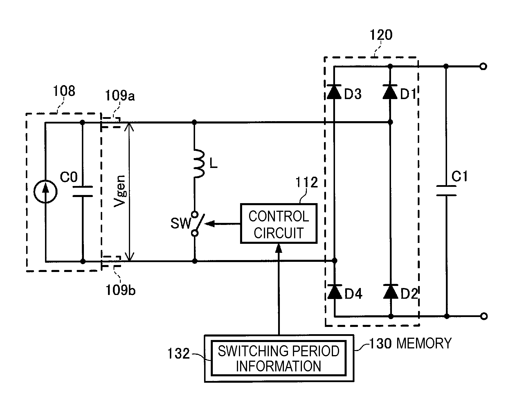
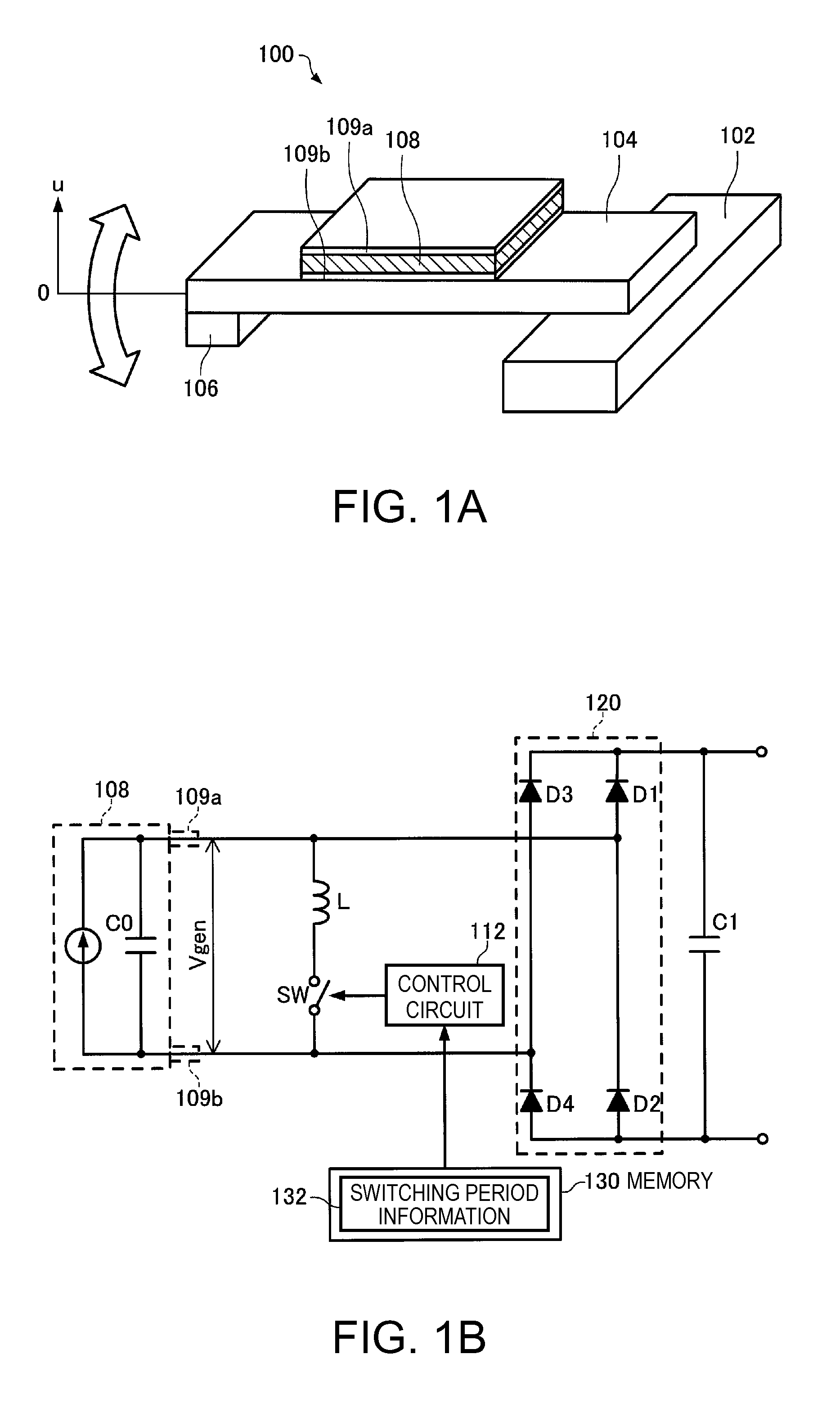
[0081]FIGS. 1A and 1B are explanatory diagrams showing a structure of a power generation unit 100 according to the present embodiment. FIG. 1A shows a mechanical structure of the power generation unit 100, and FIG. 1B shows an electrical structure thereof. The mechanical structure of the power generation unit 100 according to the present embodiment is formed as a cantilever structure in which a beam 104 having a mass 106 disposed at the tip thereof is fixed to a base 102 on the base end side thereof, and the base 102 is preferably fixed inside the power generation unit 100. Further, on the surface of the beam 104 there is attached a piezoelectric element 108 formed of a piezoelectric material such as lead zirconium titanate (PZT), and on the surfaces of the piezoelectric element 108 there are disposed a first electrode (an upper electrode) 109a and a second electrode (a lower electrode) 109b each formed of a metal thin film r...

second embodiment

B. Second Embodiment

[0127]In the power generation unit 100 according to the first embodiment, since the switch SW is set to the ON state at an arbitrary timing (with an arbitrary phase difference) independently of the state of the vibration of the beam 104, the power generation efficiency is varied dramatically due to the timing at which the switch SW is set to the ON state. Therefore, in the power generation unit 100 according to the second embodiment, the state of the vibration of the beam 104 is detected at a predetermined timing, and an adjustment is performed so that the switch SW is set to the ON state at the timing at which the deformation direction of the beam 104 is switched to thereby further improve the power generation efficiency. It should be noted that since some of the electrical power thus generated is consumed for detecting the state of the vibration of the beam 104, in particular in the power generation unit according to the second embodiment, in order to reduce th...

third embodiment

C. Third Embodiment

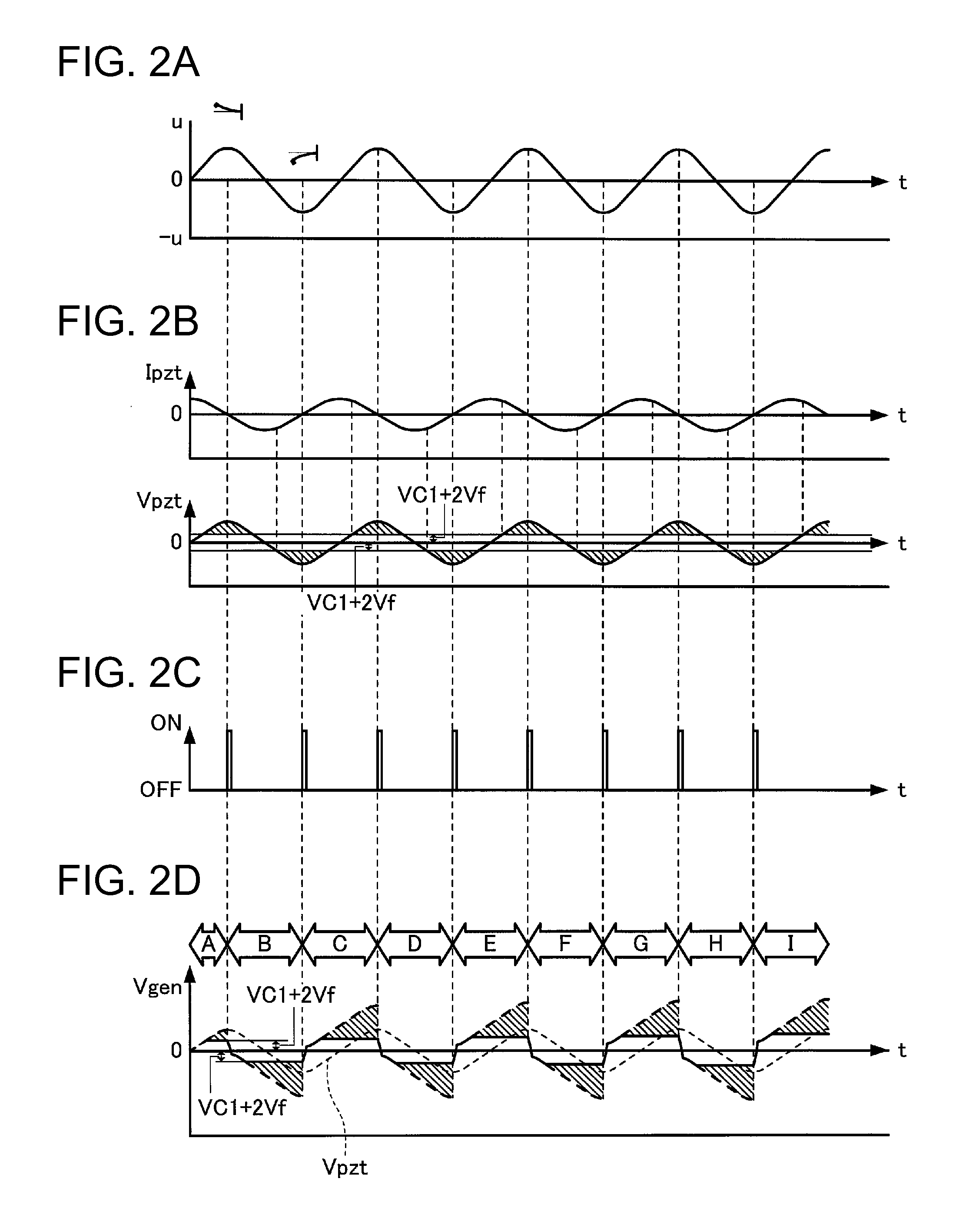
[0153]Although in the power generation unit 100 according to the second embodiment, the current flowing through the full bridge rectifier 120 is detected to thereby determine the timing at which the deformation direction of the beam 104 is switched, since the current flowing through the full bridge rectifier 120 is so minute that the exact determination is difficult in some cases. Further, since the voltage Vgen between the terminals of the piezoelectric element 108 is clipped at the voltage of the sum of VC1 and 2Vf as described above, it is unachievable to detect the peak of the voltage Vgen. Therefore, in the power generation unit 100 according to the third embodiment, a second piezoelectric element is provided to the beam 104, and the peak of the voltage generated in the second piezoelectric element is detected to thereby perform the ON / OFF control of the switch SW.

[0154]FIGS. 17A and 17B are explanatory diagrams showing a structure of the power generation uni...


PUM


Abstract

A power generation unit includes a beam (a deforming member) having a piezoelectric element and deforming while switching a deformation direction, an inductor electrically connected to the piezoelectric element, a switch disposed between the piezoelectric element and the inductor, a memory (a storage section) adapted to store switching period information (information of a characteristic vibration period of the beam), and a control circuit (a control section) adapted to control one of a timing at which the switch is set to a conductive state and a timing at which the switch is set to a nonconductive state in accordance with the switching period information stored in the memory.

Description

BACKGROUND[0001]1. Technical Field[0002]The present invention relates to a power generation unit for taking out the charge, which is generated when a piezoelectric material such as of a piezoelectric element is deformed, as electrical energy, an electronic apparatus and a transportation device using the power generation unit, and a method of controlling the power generation unit.[0003]2. Related Art[0004]When a piezoelectric material such as lead zirconium titanate (PZT), quartz crystal (SiO2), or zinc oxide (ZnO) is deformed in response to an external force, electrical polarization is induced inside the material, and positive and negative charges appear on the surfaces. Such a phenomenon is called a so-called piezoelectric effect. There has been proposed an electrical power generation method of vibrating a cantilever to thereby make a weight repeatedly act on the piezoelectric material, and thus taking out the charge generated on the surface of the piezoelectric material as electri...

Claims


Application Information

Patent Timeline
Patent Type & Authority Patents(United States)
IPC IPC(8): H02N2/18H10N30/30
CPCH01L41/1136H02N2/181H02N2/188H10N30/306
Inventor OSHIMA, ATSUSHITABATA, KUNIOYOSHINO, HIROYUKIIDE, NORITAKAHIRABAYASHI, ATSUYA
Owner SEIKO EPSON CORP
Learn More