Buck power factor correction system

Active Publication Date: 2013-04-04
IND TECH RES INST
View PDF3 Cites 12 Cited by
  • Summary
  • Abstract
  • Description
  • Claims
  • Application Information

AI Technical Summary

Problems solved by technology

A common power factor correction circuit stereotypically adopts a boost approach, which is however set back by a limitation that a direct-current output voltage is necessarily higher than a peak value of an alternating-current input voltage.
Further, although other circuits capable of outputting a lower voltage by means of buck or buck-boost are available, these circuits suffer from drawbacks from having less satisfactory characteristics and efficiency, a large volume for a corresponding storage component, complex control means to low feasibilities.
However, accompanied with a high output voltage, power components of the above conventional power factor corrector are often encountered with a higher voltage stress.
Yet, the above design increases a circuit size and production costs as well as circuit power consumption, such that conversion efficienc

Method used


Image

  • Buck power factor correction system
  • Buck power factor correction system
  • Buck power factor correction system

Examples


Example

[0029]Details of structures and concepts of the present invention shall be illustrated with embodiments below to give a better understanding on characteristics, objects and functions of the present invention.

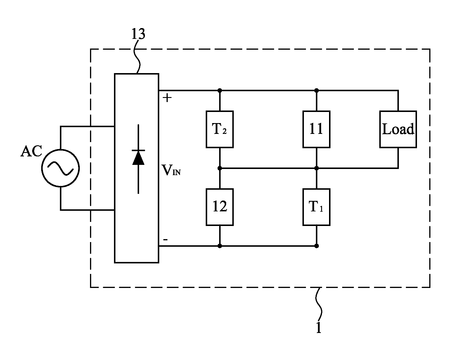
[0030]Refer to FIG. 8 showing a buck power factor correction system 1 according to an embodiment of the present invention. The buck power factor correction system 1 comprises: a first storing device 11, a first converter device T1, a second storing device 12, and a second converter device T2. The first storing device 11 is for storing and discharging energy. The first converter device T1 is coupled to the first storing device 11 is for transferring and converting energy. The second storing device 12 is coupled to the first storing device 11 is for storing and discharging energy. The second converter device T2 is coupled to the second storing device 12 is for transferring and converting energy. The buck power factor correction system 1 further comprises a rectifying device 13 and...


PUM


Abstract

The invention disclosed buck power factor correction system. The system includes: a first storing device, for storing and discharging energy; a first converter device, coupled to the first storing device, for transferring and converting energy; a second storing device, coupled to the first storing device, for storing and discharging energy; and a second converter device, coupled to the second storing device, for transferring and converting energy.

Description

TECHNICAL FIELD[0001]The present invention relates to a buck power factor correction system, and more particularly to a buck power factor correction system capable of reducing reactive power of an electronic system for providing an effect of power factor correction.TECHNICAL BACKGROUND[0002]A great number of current electrical appliances operate on direct current, and thus need direct-alternating current conversion since public electricity is alternating current. To reduce reactive power of an electronic system as well as to minimize current harmonics that cause system interference, a power factor corrector is prevailingly implemented in many electrical appliances that are required to have a high power factor and low current harmonics. A common power factor correction circuit stereotypically adopts a boost approach, which is however set back by a limitation that a direct-current output voltage is necessarily higher than a peak value of an alternating-current input voltage. Further, ...

Claims


Application Information

Patent Timeline
IPC IPC(8): G05F1/70
CPCH02M1/4208Y02B70/126H02M2001/4291H02M1/4291Y02B70/10
Inventor TSAI, WEN-TIENLEE, CHING-RAN
Owner IND TECH RES INST
Why Eureka
Try Eureka