Resource pooling amplifier

a technology of resource pooling and amplifiers, applied in the field of electromechanical power amplifiers, can solve the problems of high linearity and low cost structure, high power dissipation, and high cost of output inductors, and achieve low power dissipation

Active Publication Date: 2013-04-04
MAXIM INTEGRATED PROD INC
View PDF1 Cites 37 Cited by
  • Summary
  • Abstract
  • Description
  • Claims
  • Application Information

AI Technical Summary

Benefits of technology

[0008]According to the invention, a new type of amplifier, herein designated a resource pooling amplifier, involves extended usage of at least one inductor that is implemented by sharing. The sharing is either by switching the inductor or inductors among more than one load terminal at the same time (e.g., a bridged configuration or two different loads terminals with different polarity requirements) or by using the inductor or inductors for more than one purpose at different times. The induc...

Problems solved by technology

Class AB amplifiers are good for high linearity and low cost structure but have high power dissipation.
Most Class D amplifiers add the cost of output inductors and can p...

Method used


Image

  • Resource pooling amplifier
  • Resource pooling amplifier
  • Resource pooling amplifier

Examples


example 1

Stereo High Efficiency Headphone Amplifiers Plus One Extra DC Supply

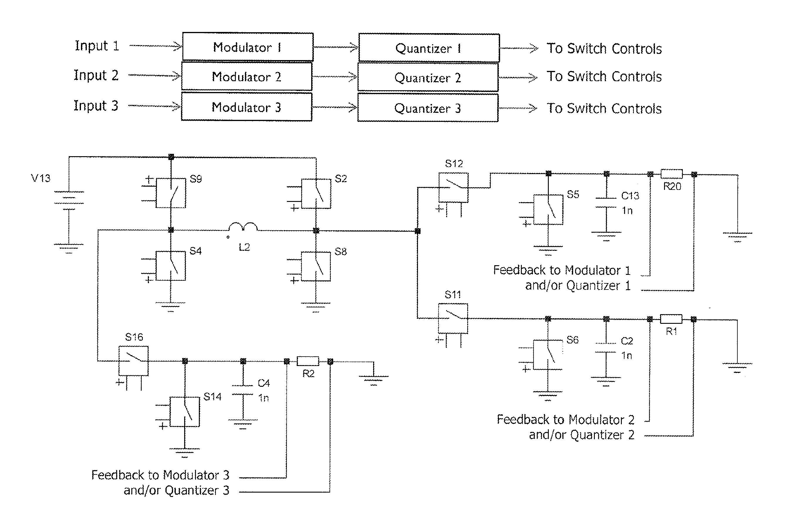
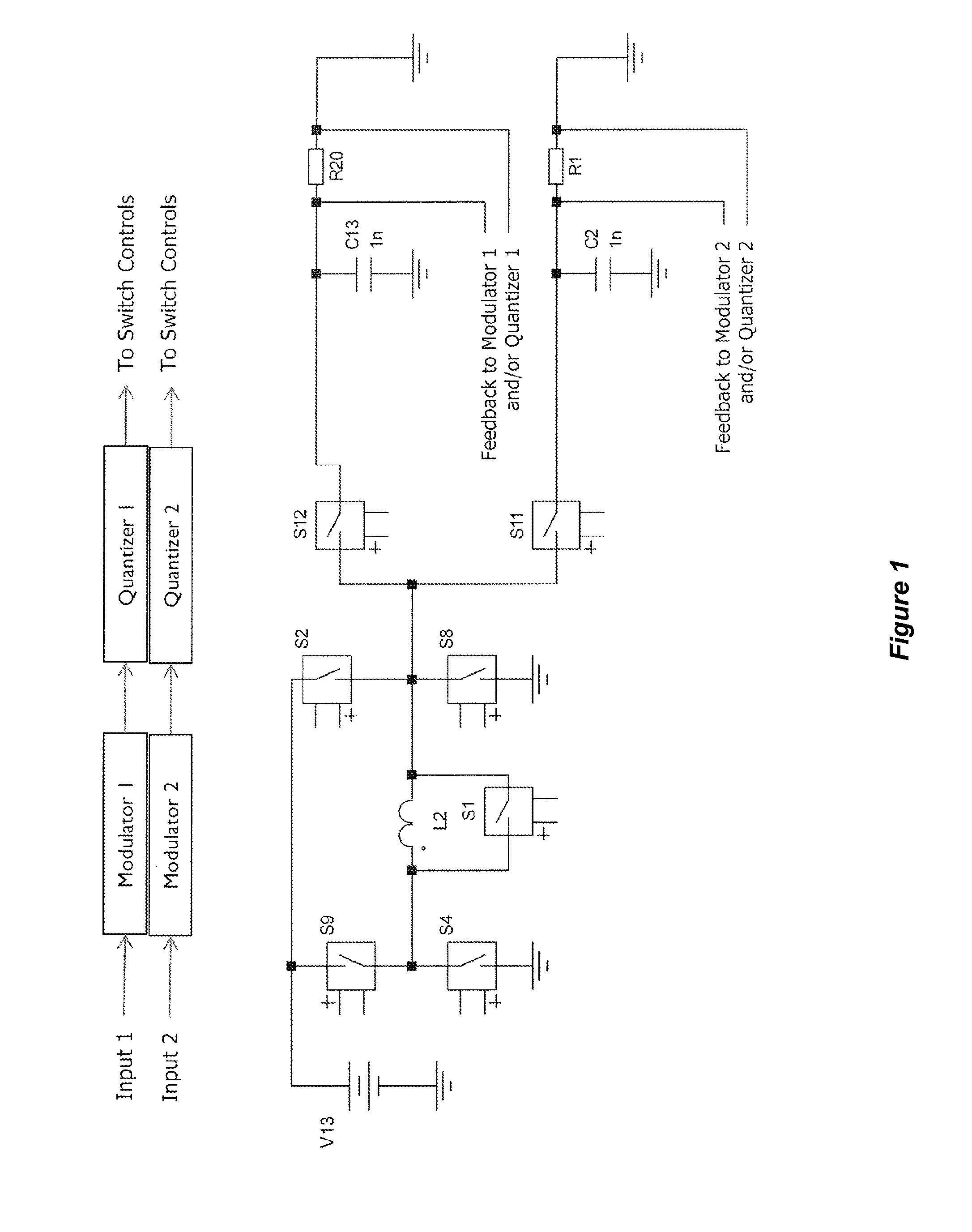
[0034]FIG. 3 show the power stage for a ground-centered stereo audio headphone amplifier with an extra DC supply. In this example, the amplifier charges the inductor and then discharges into load 1 (R20). Then it charges the inductor again and then discharges into load 2 (R1). Finally, it charges the inductor and discharges into load 3 (R2). Then this cycle repeats starting over back at load 1.

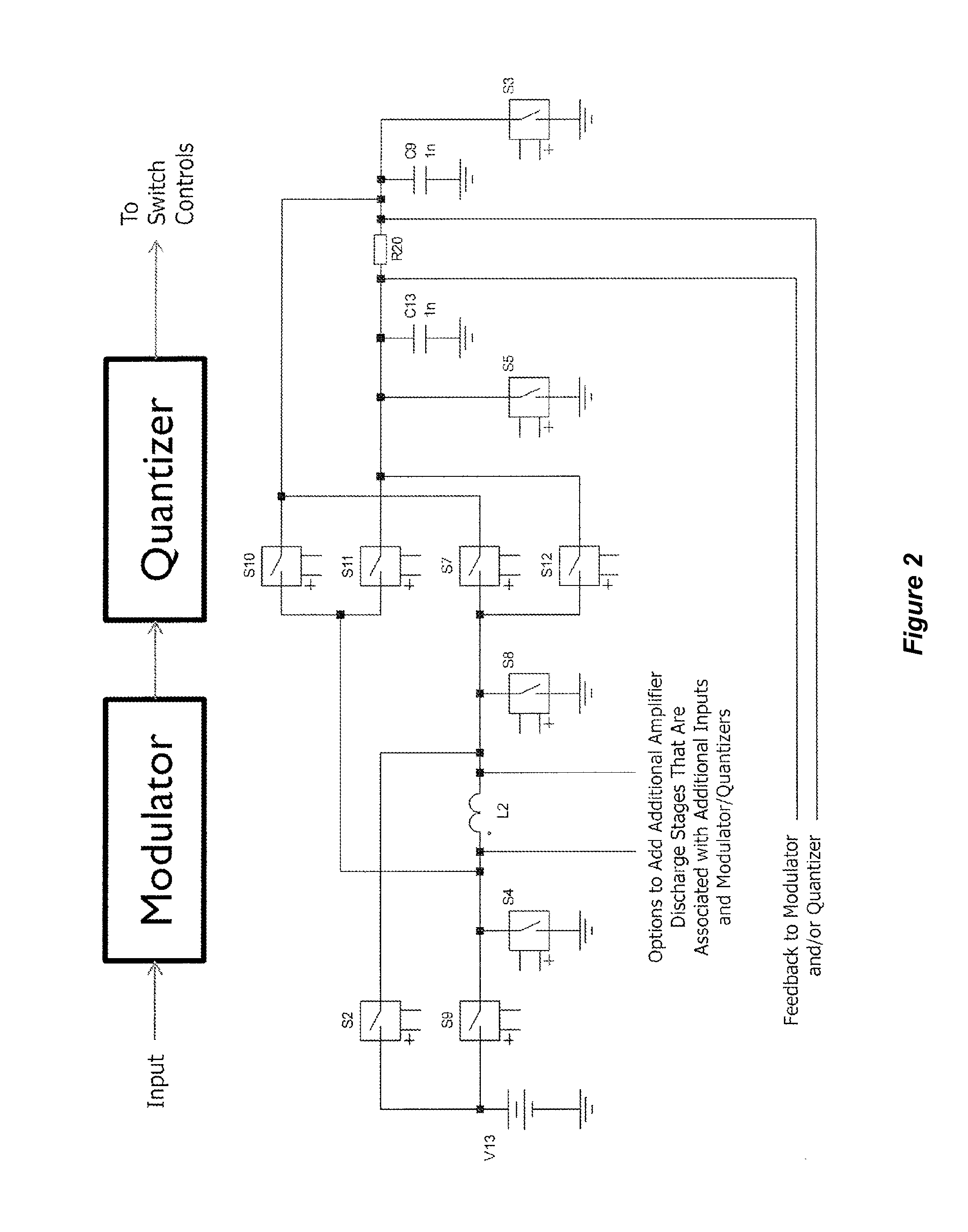
[0035]In this example, the charging is done by S9, S4, S2 and S8. These switches are shared between all of the outputs. The inductor can be charged in either polarity by either closing S8 and S9 or by closing S2 and S4.

[0036]Discharging depends on which load is being used. For R20, in this example, discharging is done by turning on S4 and either S7 or S12 with S5 and S3 respectively. For R20, in this example, discharging is done by turning on S4 and S12. For RI, in this example, discharging is done by turning on S4 and S11. Fo...

example 2

Bridged High Efficiency Amplifier Using One Inductor with Ability for Output Voltages to Exceed Supply Terminals (VCC and / or GND)

[0039]With this new art architecture, as implemented in Example 1, the inductor current can get quite high causing significant power dissipation in the amplifier. For example, even when operating in continuous boost mode, if the inductor is connected to the load 50% of the time, the average current can be approximately 2× the load current. If the inductor is cycled between many loads then the peak inductor currents can get quite high because the inductor is typically connected to the load for a small percentage of each cycle and the inductor is usually fully discharged in order to reduce crosstalk between channels. This is acceptable for loads with small output currents such as headphones but it is desirable to change this for high output power loads. Therefore, when alternating clock cycles are not being used to share the inductor with other channels as w...

example 3

Shared High Efficiency Bridged Amplifier with Either Above Headphones or Supply Rails for Class AB, Class G or Class H Headphones

[0049]In a cell phone, the high power amplifier and the headphone amplifier are rarely (if ever) used at the same time. The inductor can therefore be used for both purposes (both previous examples can share an inductor). If both are on, modulator stability may require that the high power speaker amplifier operate in a mode not using the inductor such as by adding an additional class AB amplifier.

[0050]Many new cellphones are adopting an architecture where the headphone is powered by added positive and negative supply voltages. The inductor can also be used to generate these rails (similar to first example but simply outputting fixed DC output voltages).


PUM


Abstract

A new type of amplifier, herein designated a resource pooling amplifier, involves extended usage of one or more inductors that is implemented by sharing. The sharing is either by switching the inductor or inductors among more than one load terminal at the same time (e.g., a bridged configuration or two different loads terminals with different polarity requirements) or by using the inductor or inductors for more than one purpose at different times. The inductor or inductors may be time shared such as by allocating different phases of a clock. The inductor or inductors may also be shared by monitoring load requirements and using the inductor or inductors only when needed (leaving other inductor cycles for other loads). In addition, inductor sharing may be implemented during different application requirements such as if two or more loads are not needed at the same time in a system. These types of sharing may be combined.

Description

CROSS-REFERENCES TO RELATED APPLICATIONS[0001]This application claims benefit under 35 U.S.C. 119(e) to Provisional Patent Application Ser. No. 61 / 541,397 filed Sep. 30, 2011.STATEMENT AS TO RIGHTS TO INVENTIONS MADE UNDER FEDERALLY SPONSORED RESEARCH AND DEVELOPMENT[0002]NOT APPLICABLEREFERENCE TO A “SEQUENCE LISTING,” A TABLE, OR A COMPUTER PROGRAM LISTING APPENDIX SUBMITTED ON A COMPACT DISK[0003]NOT APPLICABLEBACKGROUND OF THE INVENTION[0004]This invention relates to electronic power amplifiers.[0005]There are many different types of power amplifiers available with different tradeoffs. Class AB amplifiers are good for high linearity and low cost structure but have high power dissipation. Most Class D amplifiers add the cost of output inductors and can produce difficulties with EMI but have low power dissipation. Sometimes the power supply voltage on a Class AB amplifier is modified with a Class D regulator in order to have some of the benefits of a Class AB amplifier and some of...

Claims


Application Information

Patent Timeline
IPC IPC(8): H03F3/68H02B1/00
CPCH03F3/38H03F3/217H03F3/45928H03F3/181H03F3/005
Inventor DELANO, CARY L.
Owner MAXIM INTEGRATED PROD INC
Why Eureka
Try Eureka