Virtual image display device

a display device and virtual image technology, applied in optics, instruments, fibre light guides, etc., can solve the problems of difficult to increase the effective pupil diameter, difficulty in increasing the display size of virtual images, and blind areas, and achieve the effect of sufficient strength

Active Publication Date: 2013-04-04
SEIKO EPSON CORP
View PDF3 Cites 33 Cited by
  • Summary
  • Abstract
  • Description
  • Claims
  • Application Information

AI Technical Summary

Benefits of technology

[0009]An advantage of some aspects of the invention is to provide a virtual image display device equipped w

Problems solved by technology

However, in the device described in Document 1, since the see-through property is realized by a pupil division method using a light guide optical system with an emission opening smaller in size than the pupil, it is difficult to increase the display size of a virtual image.
Further, since the light guide optical system smaller in size than the pupil is used, it is difficult to increase the effective pupil diameter (which is the lighting diameter for enabling acquisition of a virtual image, and is also referred to as an eye ring diameter) in order to correspond to in

Method used


Image

  • Virtual image display device
  • Virtual image display device
  • Virtual image display device

Examples


second embodiment

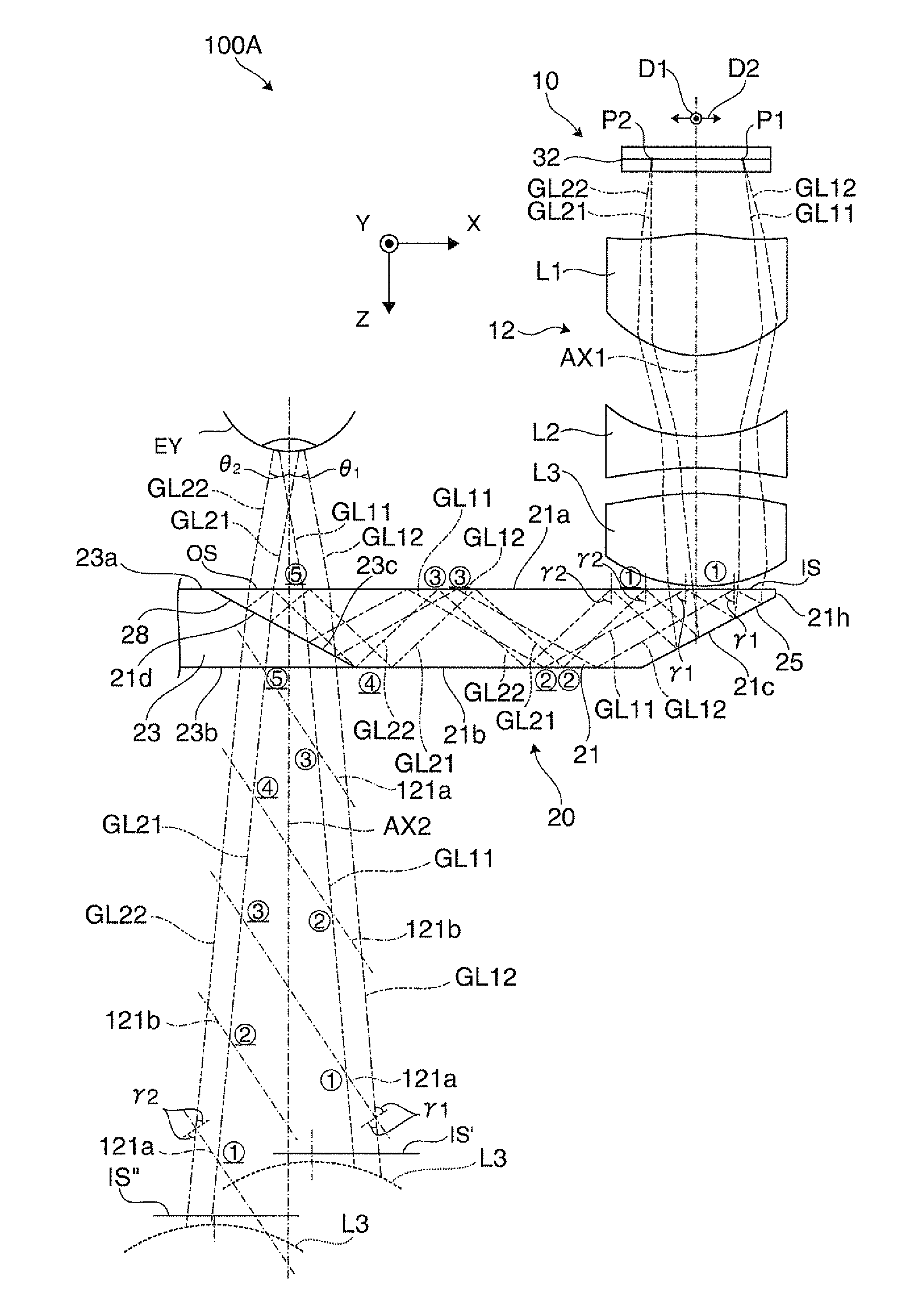
[0083]Hereinafter, a virtual image display device according to a second embodiment will be explained. It should be noted that the virtual image display device according to the present embodiment is a modified example of the virtual image display device 100 according to the first embodiment, and is assumed to be the same as the virtual image display device 100 according to the first embodiment unless particularly explained.

[0084]As shown in FIG. 10, in the case of the second embodiment, in the exceptional area PA in the first junction surface 221j of the light guide member 21, there are formed rough surfaces SR each having fine undulations 41 as nonsmooth surfaces. The rough surfaces (the nonsmooth surfaces) SR are formed by, for example, performing a roughening process in advance on a transcription surface of the molding die of the body portion 20a. Further, the rough surfaces SR can also be formed by performing a roughening process or a surface modification process such as sandblas...

third embodiment

[0089]Hereinafter, a virtual image display device according to a third embodiment will be explained. It should be noted that the virtual image display device according to the present embodiment is a modified example of the virtual image display device 100 according to the first embodiment, and is assumed to be the same as the virtual image display device 100 according to the first embodiment unless particularly explained.

[0090]As shown in FIG. 12, in the case of the third embodiment, in the exceptional area PA in the first junction surface 321j of the light guide member 21, there are formed first fitting shapes SF1, each of which is a relatively coarse undulation shape, as the nonsmooth surfaces having undulations. Each of the first fitting shapes (the nonsmooth surfaces) SF1 can be formed by arranging, for example, a number of V-grooves, which are linearly extending undulations, in a direction along the shorter dimension of the groove. On the other hand, in the opposed areas PM cor...

fourth embodiment

[0093]Hereinafter, a virtual image display device according to a fourth embodiment will be explained. It should be noted that the virtual image display device according to the present embodiment is a modified example of the virtual image display device 100 according to the first embodiment, and is assumed to be the same as the virtual image display device 100 according to the first embodiment unless particularly explained.

[0094]The virtual image display device 100 shown in FIGS. 13A through 13C is provided with the image forming device 10 and a light guide device 420 as a set. The light guide device 420 is provided with a light guide body member 21a, an angle conversion section 423, and a light transmitting body member 23s. It should be noted that FIG. 13A corresponds to the A-A cross-section of the light guide device 420 shown in FIG. 13B.

[0095]An overall appearance of the light guide body member 21s is a flat plate extending in parallel to the X-Y plane in the drawing. Further, th...


PUM


Abstract

A virtual image display device has a light guide device in which the half mirror layer (the semi-transmissive reflecting film) of the light guide member is formed on the partial area of the first junction surface, and the second junction surface of the light transmitting member is bonded to the first junction surface in at least the exceptional area. Therefore, it is possible to increase the bonding strength of the first junction surface and the second junction surface, namely the strength of the light guide device composed of the light guide member and the light transmitting member combined with each other even in the case in which the attachment force of the half mirror layer (the semi-transmissive reflecting film) with respect to the first junction surface is not sufficiently strong.

Description

BACKGROUND[0001]1. Technical Field[0002]The present invention relates to a virtual image display device such as a head-mounted display used while worn on the head.[0003]2. Related Art[0004]In recent years, as a virtual image display device such as a head-mounted display for making formation and observation of a virtual image possible, there have been proposed various devices, which are a type of guiding the image light from a display element to the pupils of the observer using a light guide plate.[0005]In such a virtual display device, in order for overlapping the image light and the external light, there has been proposed a see-through optical system (see, e.g., JP-A-2010-224473 (Document 1)).[0006]However, in the device described in Document 1, since the see-through property is realized by a pupil division method using a light guide optical system with an emission opening smaller in size than the pupil, it is difficult to increase the display size of a virtual image. Further, sinc...

Claims


Application Information

Patent Timeline
IPC IPC(8): G02B27/01
CPCG02B6/08G02B27/0176G02B2027/0178G02B2027/0125G02B27/0101G02B27/0149G02B27/0172G02B2027/0169
Inventor TAKAGI, MASAYUKITOTANI, TAKAHIROMIYAO, TOSHIAKIKOMATSU, AKIRATAKEDA, TAKASHI
Owner SEIKO EPSON CORP
Why Eureka
Try Eureka