
Secondary battery

a second battery and battery technology, applied in the field of secondary batteries, can solve the problems of less reliability of batteries and decline in battery reliability

Inactive Publication Date: 2013-04-04
SANYO ELECTRIC CO LTD
View PDF3 Cites 11 Cited by
  • Summary
  • Abstract
  • Description
  • Claims
  • Application Information

AI Technical Summary

Benefits of technology

The invention provides a secondary battery with a flat wound electrode assembly that includes a fixed separator and a fixed negative electrode substrate exposed portion, which prevents peeling and semi-floating of the negative electrode active material mixture layer at the end of the substrate exposed portion. This design reduces the likelihood of foreign materials entering the battery, resulting in higher reliability. Additionally, the invention provides a collector member that increases the contact area with the negative electrode substrate exposed portion and reduces variations in resistance. The use of a conductive intermediate member further reduces stress and the likelihood of peeling and semi-floating of the negative electrode active material mixture layer. This design also allows for stable placement of the collector member and reduces variation in internal resistance of a second battery.

Problems solved by technology

If the negative electrode active material mixture layer causes semi-floating and peeling at the end side of the negative electrode substrate exposed portion, conductive foreign materials are introduced into the battery since the negative electrode active material is conductive, and reliability of the battery declines.
A negative electrode active material mixture layer exposed at the outermost surface will be subjected to the subsequent processes to the winding and can result in less reliability of a battery because pieces of the negative electrode active material mixture layer may stick to the periphery and become contamination.

Method used


Image

  • Secondary battery
  • Secondary battery
  • Secondary battery

Examples


modification examples 1 and 2

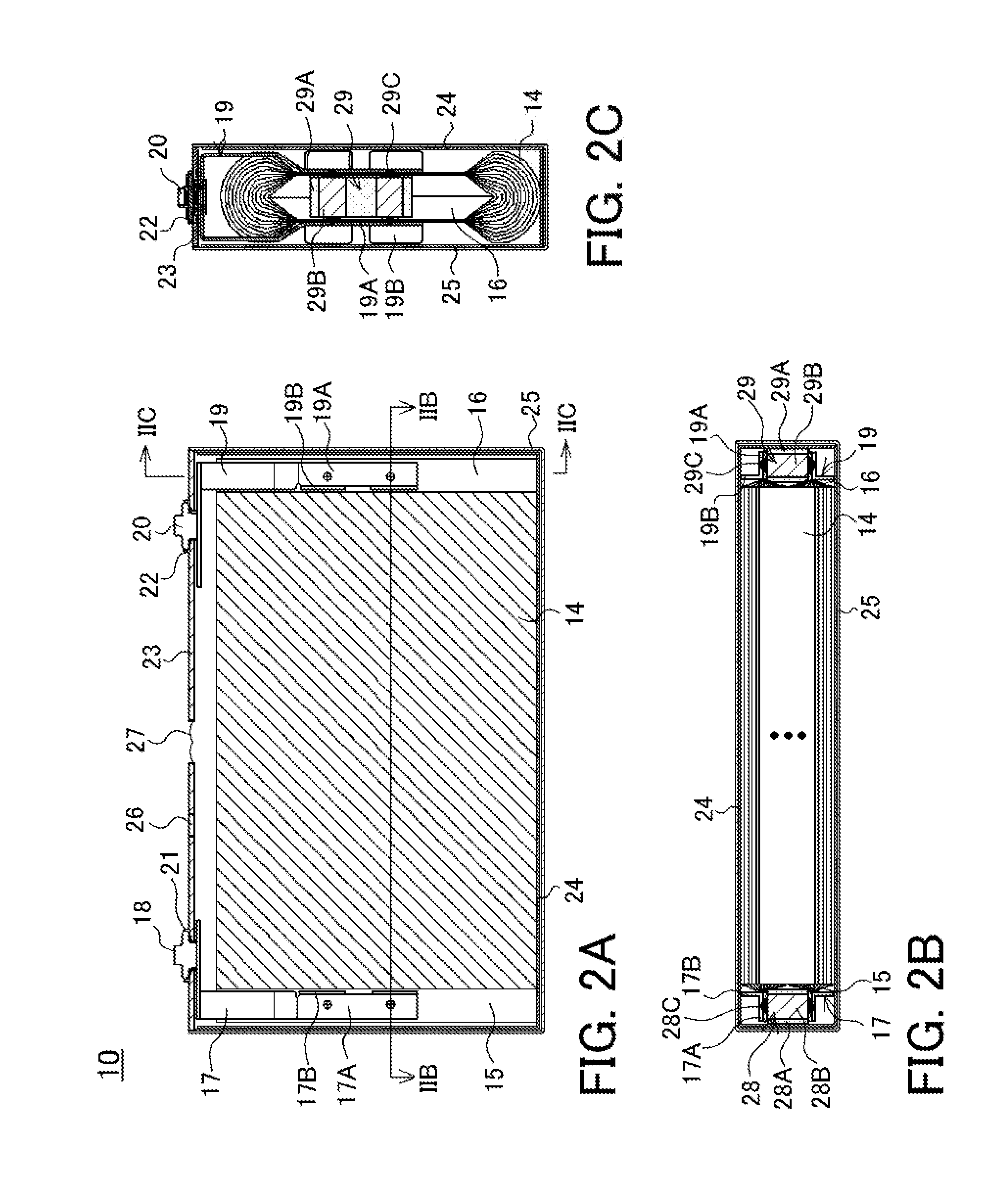
[0069]The embodiment described above has been exemplified using the negative electrode collector 19 coming into contact with both faces of the outermost surface of the bisectional negative electrode substrate exposed portion 16. It is not always necessary, however, that the negative electrode collector 19 connected to the negative electrode terminal 20 is in contact with both faces of the outermost surface of the bisectional negative electrode substrate exposed portion 16. The negative electrode collector 19 may be in contact with at least one of the faces of the outermost surface of the bisectional negative electrode substrate exposed portion 16.

[0070]The arrangement status of the negative electrode collectors 19 after resistance welding of Modification Examples 1 and 2 in which each negative electrode collector 19 connected to the negative electrode terminal 20 is in contact with one of the faces of the outermost surface of the bisectional negative electrode substrate exposed port...

modification examples 3 and 4

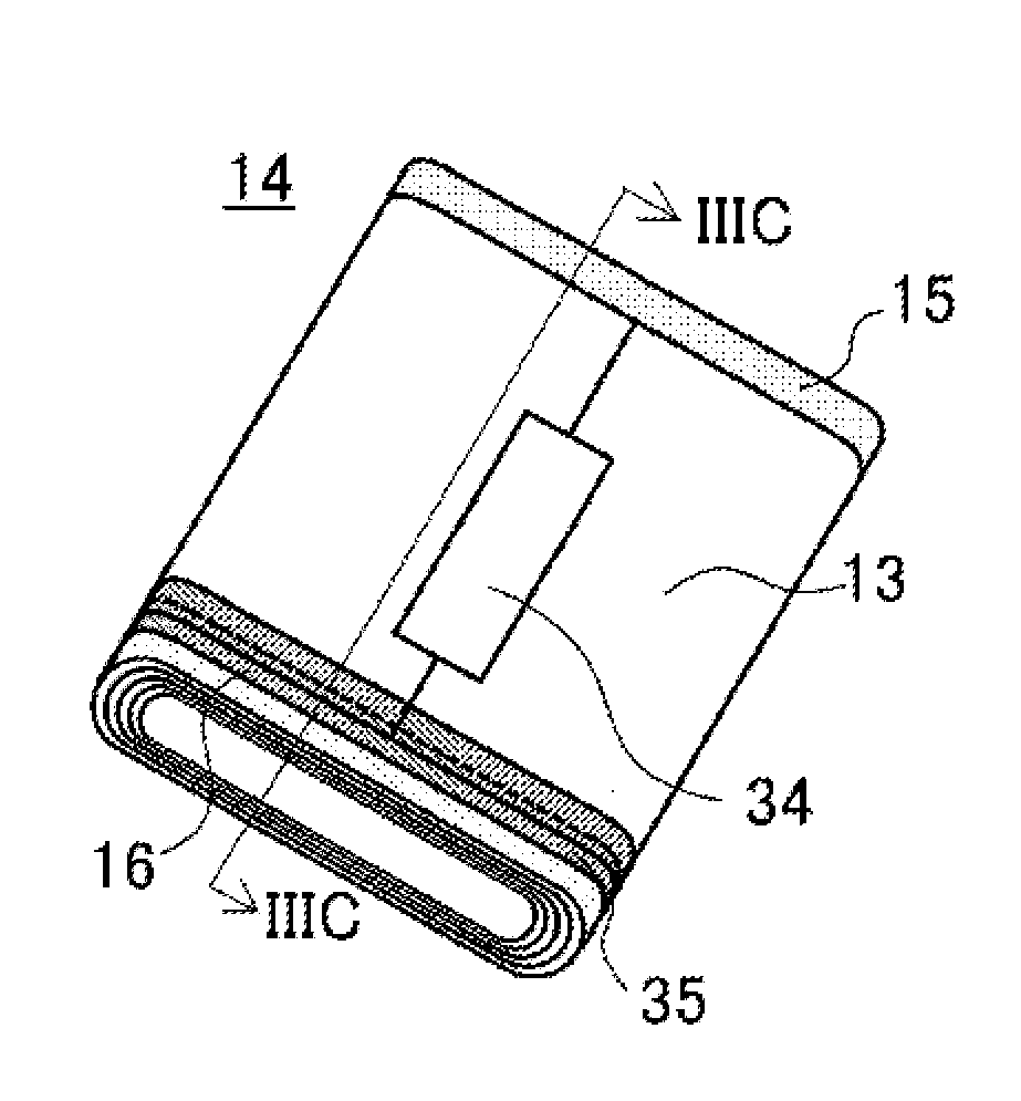
[0074]In the exemplified flat wound electrode assembly 14, as shown in FIG. 3A to FIG. 3C, the semi-floating prevention tape 35 is wound around the flat wound electrode assembly 14 at the boundary region between the separator 13 located in the outermost surface side and the negative electrode substrate exposed portion 16. In the flat wound electrode assembly, however, semi-floating and peeling of the negative electrode active material mixture layer at the outermost surface of the negative electrode plate tend to happen near corners. As Modification Example 3 shown in FIG. 6A and FIG. 6B, putting the semi-floating prevention tape 35 on each of four corners also provides excellent effects. FIG. 6A is a perspective view of a flat wound electrode assembly of Modification Example 3. FIG. 6B is a perspective view of the backside of the flat wound electrode assembly of FIG. 6A.

[0075]In the flat wound electrode assembly, when an end-of-winding portion 12b of the outermost surface of the neg...


PUM

PropertyMeasurementUnit
widthaaaaaaaaaa
thicknessaaaaaaaaaa
sizesaaaaaaaaaa

Abstract

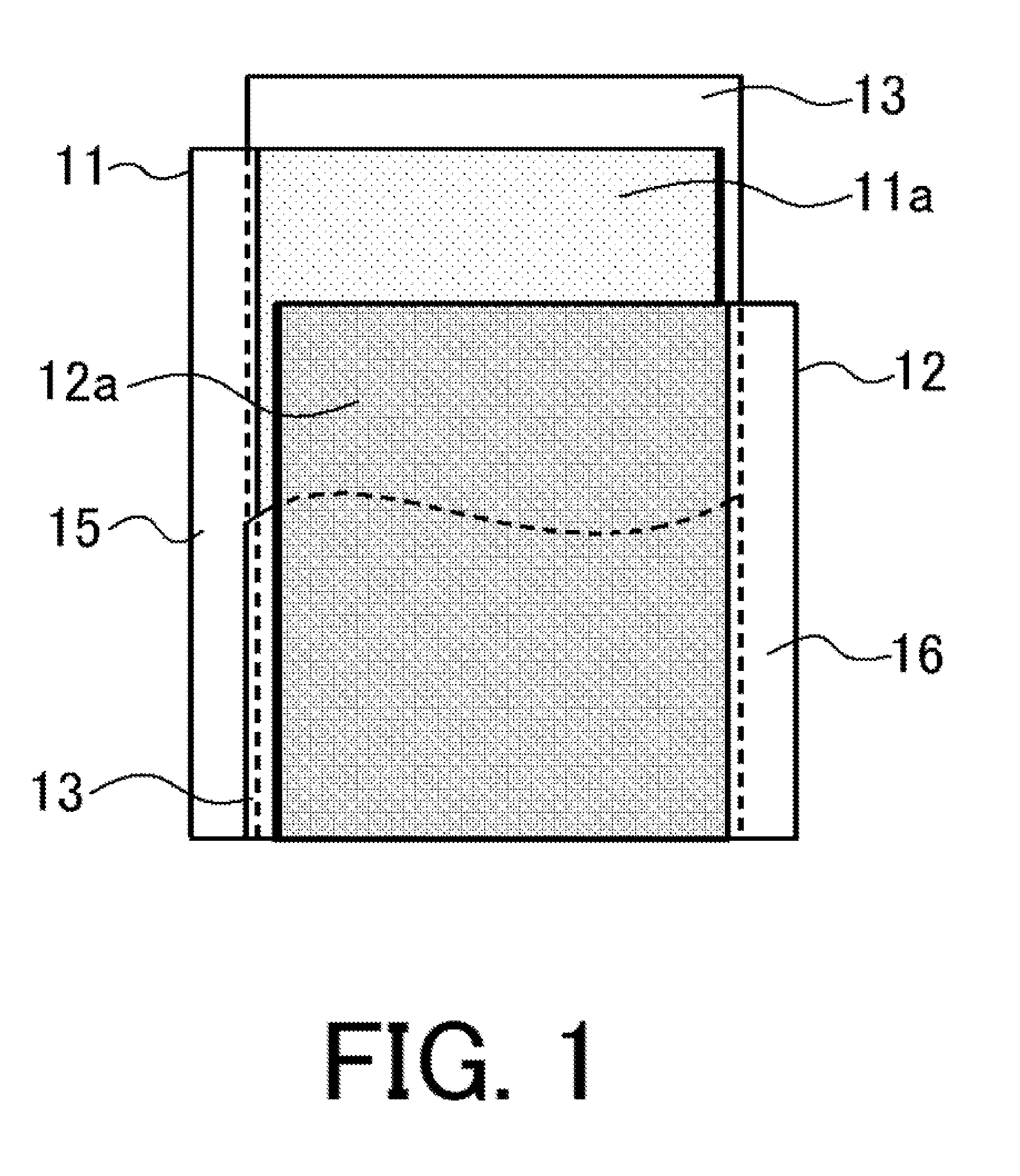
A secondary battery with a flat wound electrode assembly includes a positive and negative electrode substrate exposed portions formed on the first and second end thereof, respectively. An end portion of a negative electrode active material mixture layer of a negative electrode plate on the negative electrode substrate exposed portion side protrudes more than an end portion of positive electrode active material mixture layer of an adjacent positive electrode plate. The negative electrode substrate exposed portion is converged on the central site in the thickness direction of the electrode assembly. A separator is located at the outermost surface of the electrode assembly, and the separator and the negative electrode substrate exposed portion of the adjacent negative electrode plate are fixed integrally with a fixing member. Thereby, semi-floating and peeling of the negative electrode active material mixture layer hardly occur at the end side of the negative electrode substrate exposed portion.

Description

TECHNICAL FIELD[0001]The present invention relates to a secondary battery including a flat wound electrode assembly having higher reliability.BACKGROUND ART[0002]Secondary batteries such as lithium ion secondary batteries or nickel-hydrogen secondary batteries are widely used as driving power sources for mobile electronic apparatuses such as contemporary mobile telephones, portable personal computers, and portable music players, or as power sources for hybrid electric vehicles (HEVs, PHEVs) and electric vehicles (EVs). As such secondary batteries, prismatic secondary batteries rather than cylindrical secondary batteries are highly needed in particular when space efficiency is required.[0003]A prismatic secondary battery, in particular, a prismatic nonaqueous electrolyte secondary battery is produced as follows. A negative electrode plate with negative electrode active material mixture layers including a negative electrode active material in both faces of a negative electrode substra...

Claims


Application Information

Patent Timeline
Patent Type & Authority Applications(United States)
IPC IPC(8): H01M4/70H01M2/18H01M50/538
CPCH01M10/04H01M4/02H01M10/0431Y02E60/10Y02P70/50
Inventor NONAKA, TAIKIFUJIHARA, TOYOKI
Owner SANYO ELECTRIC CO LTD
Learn More