Power storage device

Active Publication Date: 2013-04-04
SEMICON ENERGY LAB CO LTD
View PDF4 Cites 10 Cited by
  • Summary
  • Abstract
  • Description
  • Claims
  • Application Information

AI Technical Summary

Benefits of technology

The patent text explains that when a layer of silicon is placed over a current collector and covered with a layer of graphite, the thickness of the graphite layer can negatively impact the performance of a power storage device. This leads to lower capacity and slower charging / discharging times. The technical effect of this patent is to provide a solution to improve the performance of power storage devices by overcoming the challenges presented by thick graphite layers.

Problems solved by technology

These problems reduce reaction between silicon and carrier ions, resulting in lower charge / discharge capacity and slower charge / discharge of a power storage device.
In addition, even in the case where active material particles are covered with a graphene, it is difficult to suppress expansion of the volume of the particles of the active material due to repeated charge / discharge and the resulting pulverization of the particles of the active material.

Method used


Image

  • Power storage device
  • Power storage device
  • Power storage device

Examples


embodiment 1

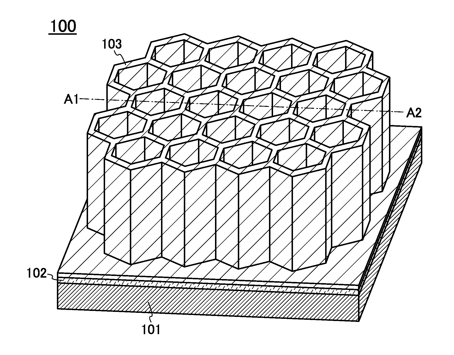
[0046]In this embodiment, an example of a structure of a negative electrode for a power storage device which is unlikely to be degraded by charge / discharge and has good charge / discharge cycle characteristics and an example of a method of manufacturing the negative electrode are described with reference to FIGS. 1A and 1B, FIGS. 2A and 2B, FIGS. 3A and 3B, FIGS. 4A and 4B, FIGS. 5A to 5C, FIGS. 6A and 6B, FIGS. 7A to 7C, and FIGS. 8A to 8C.

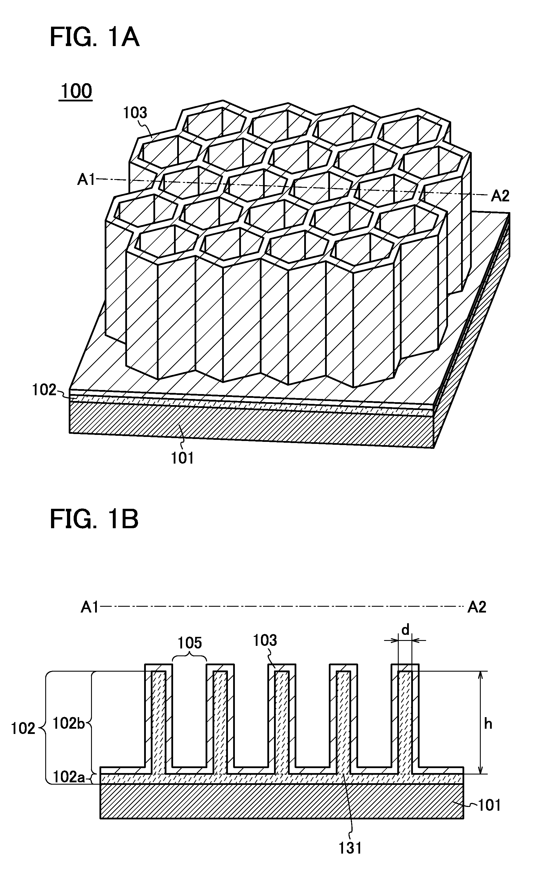
[0047]FIG. 1A is a perspective view illustrating part of a negative electrode 100. FIG. 1B is a cross-sectional view of the negative electrode 100 taken along the line A1-A2 in FIG. 1A. The negative electrode 100 includes, over a current collector 101, an active material layer 102 which has a surface having a plurality of cavities. In this embodiment, a graphene 103 covering the active material layer 102 is provided over the negative electrode 100.

[0048]Note that the term active material refers to a substance that relates to occlusion and release o...

embodiment 2

[0105]In this embodiment, examples of a structure of a power storage device and a manufacturing method thereof are described.

[0106]First, examples of a positive electrode and a manufacturing method thereof are described.

[0107]FIG. 9A is a cross-sectional view of a positive electrode 311. In the positive electrode 311, a positive electrode active material layer 309 is formed over a positive electrode current collector 307.

[0108]As the positive electrode current collector 307, a material having high electric conductivity such as platinum, aluminum, copper, titanium, or stainless steel can be used. The positive electrode current collector 307 can have a foil-like shape, a plate-like shape, a net-like shape, or the like as appropriate.

[0109]As the positive electrode active material layer 309, LiFeO2, LiCoO2, LiNiO2, LiMn2O4, V2O5, Cr2O5, MnO2, or the like can be used as a material.

[0110]Alternatively, an olivine-type lithium-containing composite oxide (a general formula LiMPO4 (M is one...

embodiment 3

[0149]A power storage device in accordance with one embodiment of the present invention can be used as a power supply of various electronic appliances which are driven by electric power.

[0150]Specific examples of electronic appliances using the power storage device of one embodiment of the present invention are display devices, lighting devices, desktop personal computers, laptop personal computers, image playback devices which reproduce a still image or a moving image stored in recording media such as digital versatile discs (DVDs), mobile phones, portable game machines, portable information terminals, e-book readers, cameras such as video cameras and digital still cameras, high-frequency heating apparatuses such as microwaves, electric rice cookers, electric washing machines, air-conditioning systems such as air conditioners, electric refrigerators, electric freezers, electric refrigerator-freezers, freezers for preserving DNA, dialysis devices, and the like. Another examples of t...


PUM


Abstract

Provided are an electrode for a power storage device having much better charge / discharge characteristics and a power storage device using the electrode. A plurality of cavities is provided in a surface of an active material layer over a current collector. A graphene covering the active material layer facilitates rapid charge / discharge and prevents breakdown of the current collector caused by charge / discharge. With improved charge / discharge characteristics, an electrode for a power storage device which does not easily deteriorate and a power storage device using the electrode can be provided.

Description

BACKGROUND OF THE INVENTION[0001]1. Field of the Invention[0002]The present invention relates to a negative electrode for a power storage device and a method of manufacturing a power storage device using the negative electrode.[0003]2. Description of the Related Art[0004]In recent years, power storage devices such as lithium secondary batteries, lithium-ion capacitors, and air cells have been developed.[0005]A power storage device has two electrodes: a positive electrode and a negative electrode. To provide a negative electrode for a power storage device, an active material is formed over a surface of a current collector. As a negative electrode active material, a material that can occlude and release ions functioning as carriers (hereinafter referred to as carrier ions), such as carbon or silicon, is used. Silicon or phosphorus-doped silicon, for example, is beneficial to the higher capacity of a power storage device because they can occlude about four times as many carrier ions as...

Claims


Application Information

Patent Timeline
IPC IPC(8): H01M4/70H01M4/38H01M4/583B82Y30/00H01M50/469
CPCH01M4/134H01M10/0525Y02E60/122H01M2/1673H01M2004/027H01M4/366H01M4/587H01M4/625H01M2004/025H01M2/18Y02E60/10H01M50/46H01M50/469
Inventor OSADA, TAKESHITAJIMA, RYOTAOGUNI, TEPPEIYAMAZAKI, SHUNPEI
Owner SEMICON ENERGY LAB CO LTD
Why Eureka
Try Eureka