
Process and apparatus for overlay welding

a technology of overlay welding and welding apparatus, which is applied in the direction of mechanical equipment, machines/engines, manufacturing tools, etc., can solve the problems of high cost of lbw equipment, complex reinforcement or repair of substrates with overlay welding, and low deposition rate, so as to reduce the dilution of substrate materials

Inactive Publication Date: 2013-04-11
GENERAL ELECTRIC CO
View PDF17 Cites 7 Cited by
  • Summary
  • Abstract
  • Description
  • Claims
  • Application Information

AI Technical Summary

Benefits of technology

This invention describes a way to weld a layer of material onto a substrate in a way that minimizes the impact on the substrate, while still creating a strong bond between the two materials. This process can use traditional arc welding techniques instead of more expensive laser beam welding, allowing for faster deposition rates.

Problems solved by technology

As such, the reinforcement or repair of a substrate with an overlay weld can be complicated by the desire to reduce intermixing of the overlay weld material with the substrate material, in contrast to certain welding methods where intermixing is desirable.
However, a drawback of LBW is that deposition rates tend to be very low and LBW equipment can be cost prohibitive.
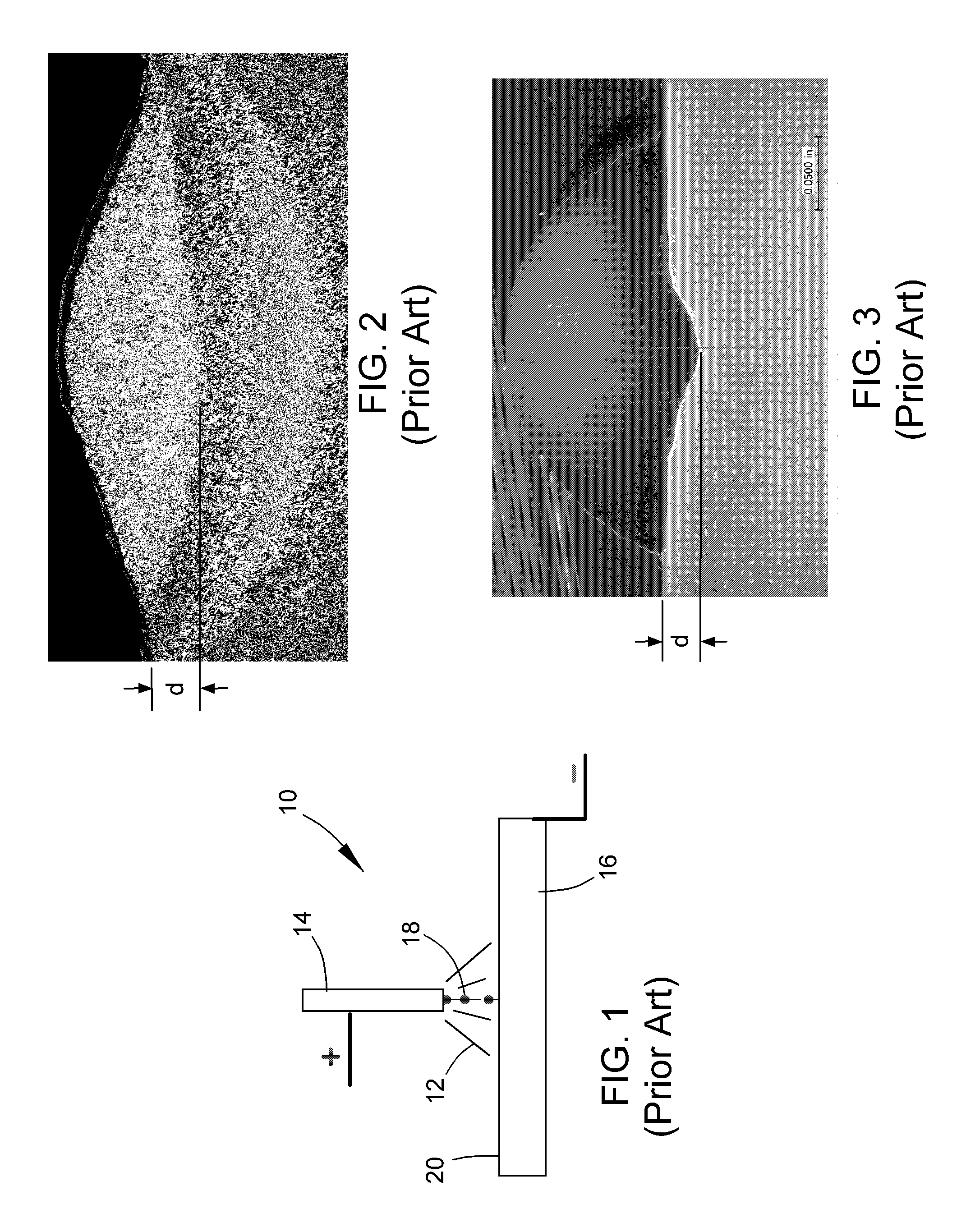
Though significantly less than the weld penetration evidenced in FIG. 2, the penetration seen in FIG. 3 can still be excessive, for example, in the aforementioned manifold application.

Method used


Image

  • Process and apparatus for overlay welding
  • Process and apparatus for overlay welding
  • Process and apparatus for overlay welding

Examples


Embodiment Construction

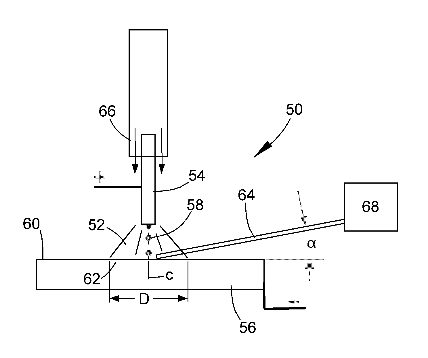
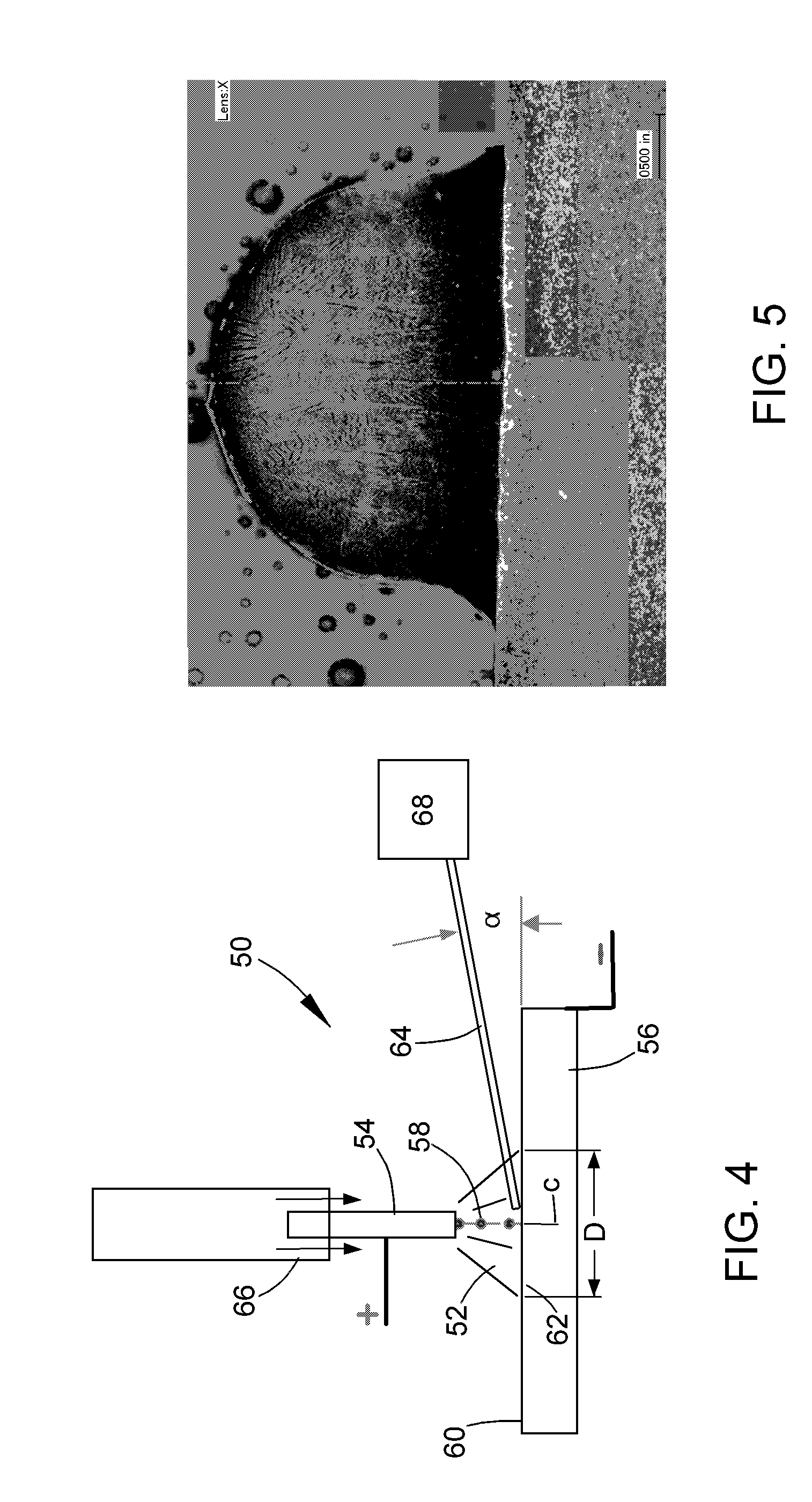
[0018]The present invention provides the capability of reducing the depth of penetration of an overlay weld produced by an arc welding process that uses a consumable electrode, a particular example of which is GMAW (MIG). An example of a welding apparatus suitable for use with the invention is schematically represented as a GMAW apparatus 50 in FIG. 4, though it should be understood that the invention can be extended to other arc welding processes that utilize an electrode that is consumed during the overlay welding process. In addition, the invention is generally applicable to welding a wide variety of materials, including nickel-, cobalt- and iron-base superalloys, stainless steels, carbon steels, Cr—Mo steels, low-alloy steels, etc.

[0019]Similar to the prior art apparatus 10 of FIG. 1, the apparatus 50 of FIG. 4 is schematically represented as generating an electrical arc 52 between a consumable electrode 54 and a substrate 56 to be welded. As known in the art, a suitable welding...


PUM

PropertyMeasurementUnit
angleaaaaaaaaaa
fusion depthaaaaaaaaaa
fusion areaaaaaaaaaaa

Abstract

An apparatus and process for depositing an overlay weld on a substrate in a manner that reduces dilution of the substrate material. A consumable electrode is positioned in proximity to the surface of the substrate, and an electrical potential is applied between the electrode and substrate to generate an electrical arc therebetween. The arc melts the electrode and forms a molten spray that deposits on the substrate surface. Energy of the electric arc is absorbed to reduce the temperature at the substrate surface by feeding an additional filler material into the electric arc toward its center axis. The filler material continuously melts prior to reaching the center axis of the electric arc, and the electrode and filler materials are simultaneously deposited to form the overlay weld on the substrate. Sufficient energy is absorbed by the filler material to reduce intermixing between the overlay weld and the substrate.

Description

BACKGROUND OF THE INVENTION[0001]The present invention generally relates to welding equipment and processes. More particularly, this invention relates to a welding apparatus and process for depositing an overlay weld such that mixing and dilution between the base metal and a deposited metal is reduced by reducing the depth of penetration of the deposited metal, and therefore the overlay weld, into the base metal.[0002]Overlay welding generally involves depositing weld material over a surface region of a substrate. The weld material may be deposited as a series of beads, often with some lateral overlapping to form a continuous cladding layer of weld material that increases the thickness of the substrate, as well as properties such as strength. Overlay welds are utilized in a wide variety of applications, including but not limited to the fabrication and restoration of relatively large vessels and tubes used in industries such as utilities (including power generation), co-generation re...

Claims


Application Information

Patent Timeline
Patent Type & Authority Applications(United States)
IPC IPC(8): F02C7/22B23K9/04
CPCF02C7/222F05D2230/80B23K9/042F05D2230/31F05D2230/232
Inventor LIN, DECHAOKOTTILINGAM, SRIKANTH CHANDRUDUCUI, YANUCOK, IBRAHIMTOLLISON, BRIAN LEE
Owner GENERAL ELECTRIC CO
Learn More