Gas safety device

a safety device and gas technology, applied in the direction of gaseous heating fuel, failure to burn, combustion apparatus installed at the cooking utensils always has a risk of accidents, food being burned,

Active Publication Date: 2013-04-11
KIODDE CO LTD
View PDF5 Cites 1 Cited by
  • Summary
  • Abstract
  • Description
  • Claims
  • Application Information

AI Technical Summary

Benefits of technology

[0020]As described above, since the gas safety device according to the present invention is configured to close an electronic valve connected to a thermocouple to cut off a gas supply when the temperature of radiant heat directly emitted from a surface of a vessel exceeds a preset temperature level while the vessel is heated through spark ignition of a burner, risks of overheating and thus fire caused due to a user's carelessness when the user cooks food can be prevented.

Problems solved by technology

When the heating point of contact of the thermocouple is not increased to the predetermined temperature, the sparks are ignited from the spark plug, but the heating operation is not performed with gas combustion in the burner.
Meanwhile, the combustion apparatus installed at the cooking appliances always has a risk of accidents since the gas is used as a fuel.
In one example, when a user forgets that food is being cooked using a cooking appliance, a vessel carrying the food is over-heated, resulting in the vessel being blackened and the food being burned, or even in a conflagration.
However, the gas safety device does not precisely detect a heating state of the vessel since the gas safety device senses the sparks of the burner and converts the sparks into an electrical signal.
Therefore, the conventional gas safety devices often malfunctions because the gas supply through the electronic valve is not cut off when the running temperature of the thermocouple does not reach a temperature of approximately 600° C. even though the moisture content in the vessel is completely evaporated at a temperature of approximately 100 to 150° C. and a surface of the vessel is blackened.

Method used


Image

  • Gas safety device
  • Gas safety device
  • Gas safety device

Examples


Embodiment Construction

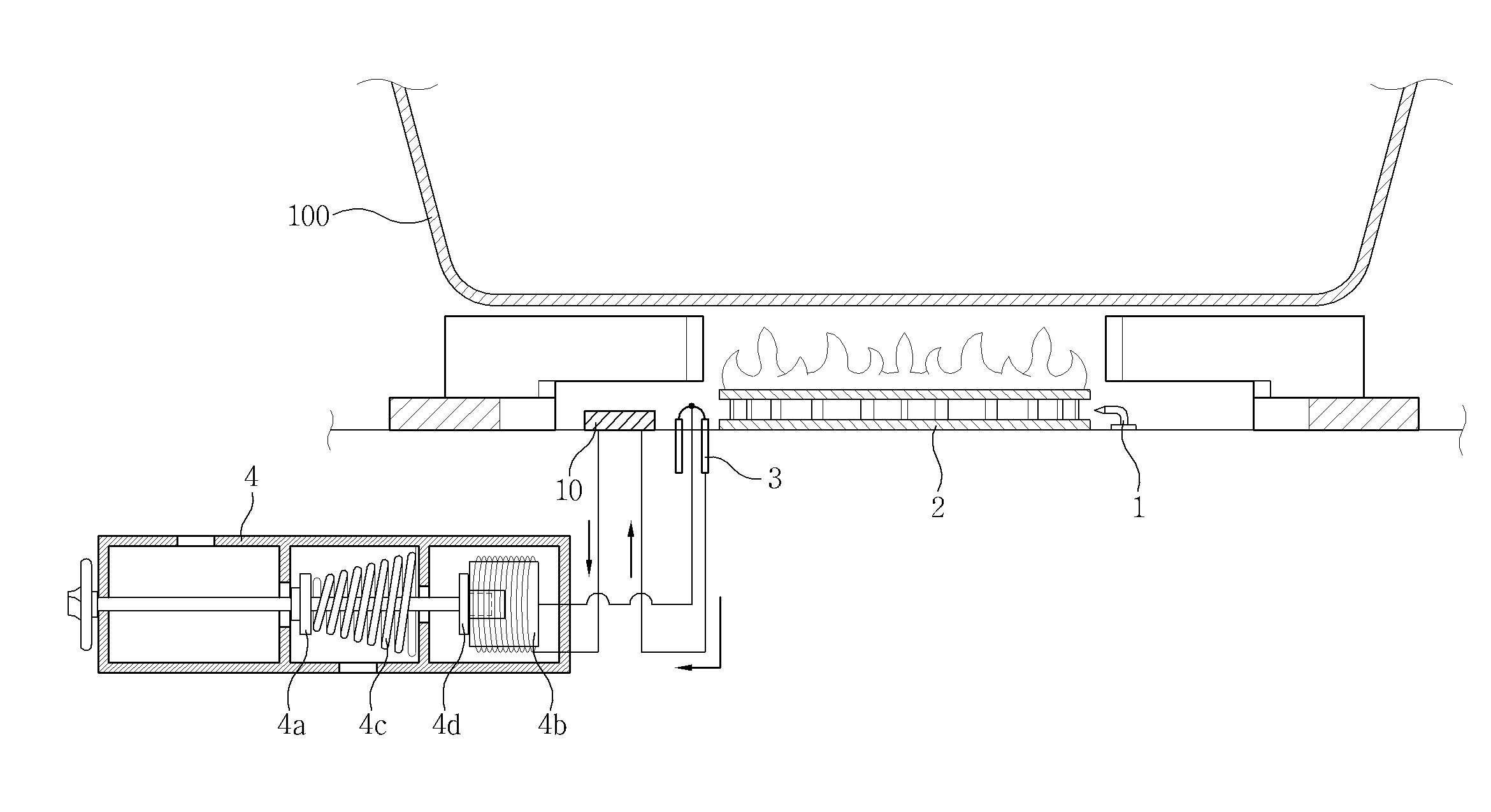
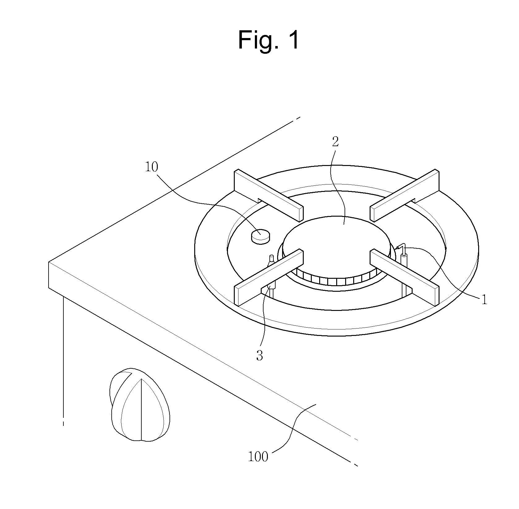
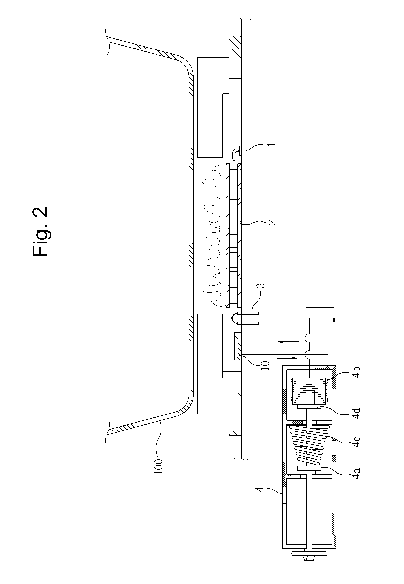
[0032]As described above, the gas safety device according to one exemplary embodiment of the present invention is configured to generate a thermoelectromotive force of approximately 20 to 750 mV in the thermocouple 3 formed at one side of the burner 2 when the vessel 100 is heated as the burner 2 is turned on through an igniting operation of the spark plug 1 in a state in which the vessel 100 containing the contents to be cooked is put on the burner 2, as shown in FIGS. 1 to 3.

[0033]In this case, the radiant heat is radially emitted when the vessel 100 is heated. Then, when the temperature of the emitted radiant heat does not exceed a preset temperature level of 160° C., the bimetal switch that is the safety switching unit 10 configured to be exposed to one side of the burner 2 is in a switched-on mode. Therefore, the generated thermoelectromotive force is transferred to the electromagnet4b in the electronic valve unit 4 via the line L2 and the bimetal switch that is the safety swit...


PUM


Abstract

A gas safety device is provided. An electronic valve connected to a thermocouple is closed to cut off the gas supply when the temperature of radiant heat directly emitted from a surface of a vessel exceeds a preset temperature level while the vessel is heated through the spark ignition of a burner, thereby preventing risks of overheating and thus fire caused due to a user's carelessness when the user cooks the food.

Description

TECHNICAL FIELD[0001]The present invention relates to a gas safety device capable of automatically cutting off the gas supply in a cooking appliance (for example, a gas range, a gas oven range, a gas burner, etc.), and, more particularly, to a gas safety device capable of preventing the risk of fire caused by overheating while food is cooked in a cooking appliance.BACKGROUND ART[0002]In general, a combustion apparatus, which is applied in cooking appliances using liquefied natural gas (LNG) or liquefied petroleum gas (LPG) as a fuel, performs a heating operation as sparks are ignited by bringing a gas fuel in contact with air. The heating from the combustion apparatus results in food being cooked.[0003]That is, the cooking appliance is made of a metal, and includes a cooking body composed of one or plural grills on which a cooking vessel is placed, and a combustion apparatus formed in the grills.[0004]In this case, the combustion apparatus is composed of a burner, a spark plug, and ...

Claims


Application Information

Patent Timeline
Patent Type & Authority Applications(United States)
IPC IPC(8): F24C3/12
CPCF23K5/007F23K2900/05001F23N5/105F24C3/126F23N2031/00F23N2035/24F23N2041/08F23N5/245F23N2231/00F23N2235/24F23N2241/08Y10T137/1516Y10T137/1963Y10T137/1987
Inventor PARK, SUNG-HYUNG
Owner KIODDE CO LTD
Why Eureka
Try Eureka