Electronic parking brake

a technology of electronic brakes and parking brakes, applied in the direction of brake systems, mechanical equipment, transportation and packaging, etc., can solve the problems of reducing the utilization of indoor space of vehicles, increasing the number of vehicles, and increasing the man-hours of assembly, so as to reduce the generated rotating force, improve the connection structure, and minimize the length

Active Publication Date: 2013-04-11
HL MANDO CORP
View PDF4 Cites 49 Cited by
  • Summary
  • Abstract
  • Description
  • Claims
  • Application Information

AI Technical Summary

Benefits of technology

[0011]Therefore, it is an aspect of the present invention to provide an electronic parking brake which reduces rotating force generated from

Problems solved by technology

However, such a conventional manual type parking brake may cause problems, such as inconvenience in that a driver needs to pull the parking lever by proper force, increase in the number of parts, such as a

Method used


Image

  • Electronic parking brake
  • Electronic parking brake
  • Electronic parking brake

Examples


Embodiment Construction

[0025]Reference will now be made in detail to the embodiments of the present invention, examples of which are illustrated in the accompanying drawings, wherein like reference numerals refer to like elements throughout. The terms used in the following description are terms defined taking into consideration the functions obtained in accordance with the embodiments, and the definitions of these terms should be determined based on the overall content of this specification. Therefore, the configurations disclosed in the embodiments and the drawings of the present invention are only exemplary and do not encompass the full technical spirit of the invention, and thus it will be appreciated that the embodiments may be variously modified and changed.

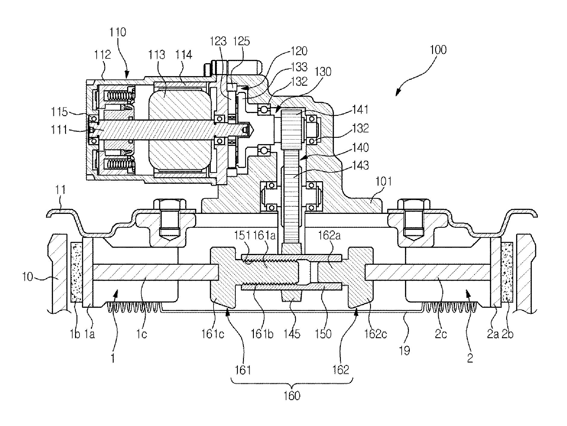
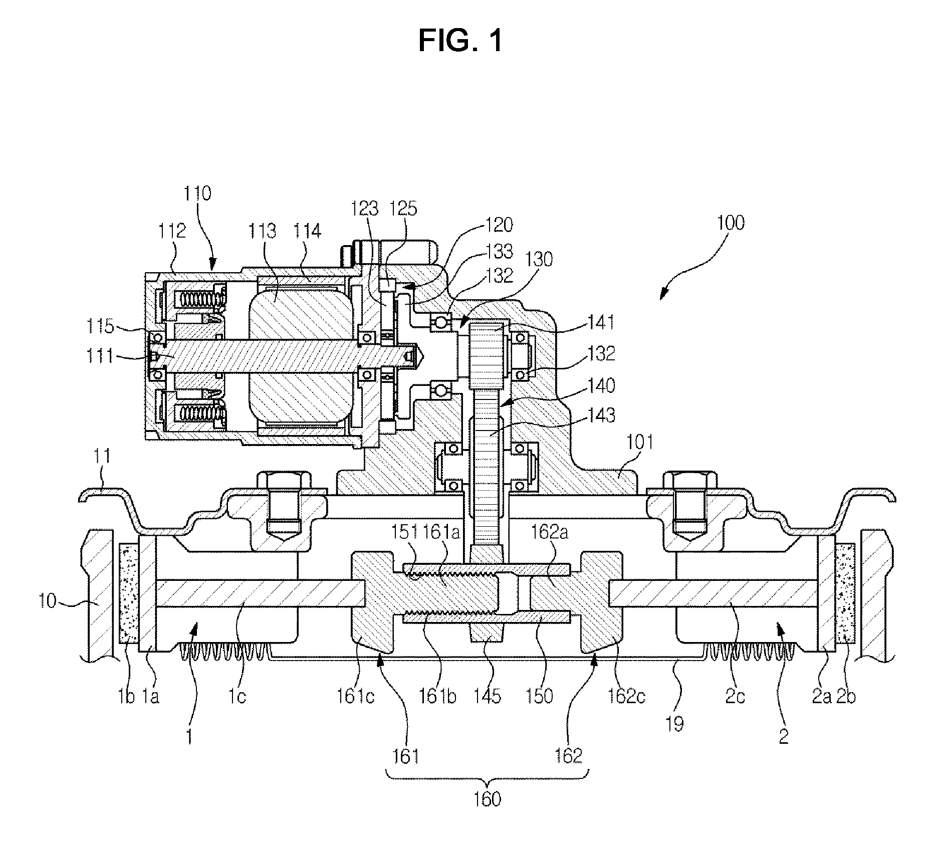
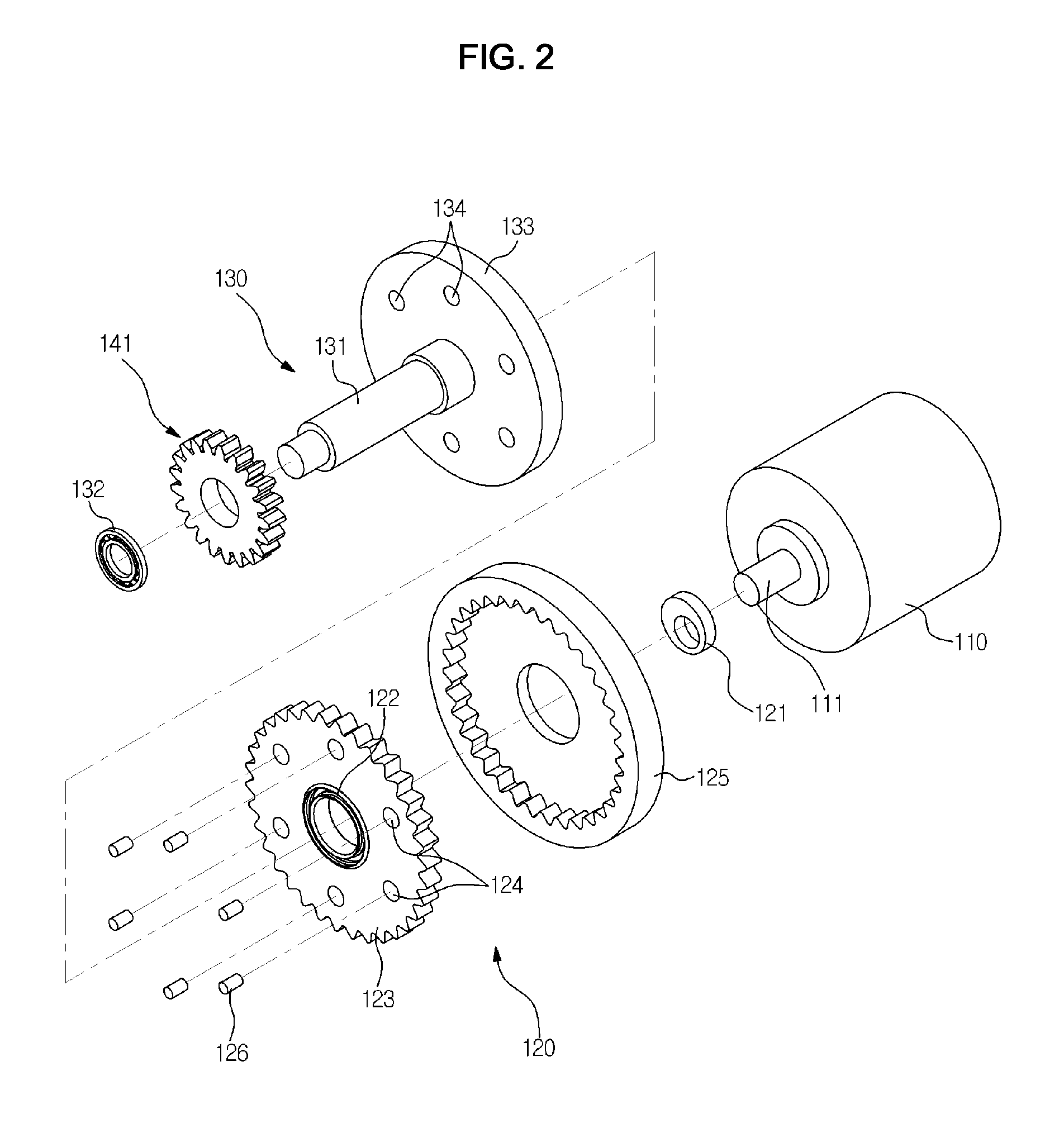
[0026]FIG. 1 is a longitudinal-sectional view schematically illustrating an electronic parking brake in accordance with one embodiment of the present invention, and FIG. 2 is an exploded perspective view illustrating a motor, a cycloid reducer and...


PUM


Abstract

Disclosed herein is an electronic parking brake which is installed in a vehicle and is operated by a motor. The electronic parking brake having a drum rotating together with a wheel and first and second brake shoes includes a motor rotated in normal and reverse directions and generating driving force for braking, a cycloid reducer connected to a rotary shaft of the motor and amplifying the driving force generated from the motor, a spindle member connected to the cycloid reducer and rotated, a spur gear assembly rotated by rotary force transmitted from the spindle member, a piston rotated and provided with the outer circumferential surface on which one gear of the spur gear assembly is integrally formed, and a push rod unit installed at both ends of the piston in the longitudinal direction, rectilinearly moved according to rotation of the piston and supported by the first and second brake shoes.

Description

CROSS-REFERENCE TO RELATED APPLICATION[0001]This application claims the benefit of Korean Patent Application No. 2011-0102377, filed on Oct. 7, 2011 in the Korean Intellectual Property Office, the disclosure of which is incorporated herein by reference.BACKGROUND[0002]1. Field[0003]Embodiments of the present invention relate to an electronic parking brake which is installed in a vehicle and is operated by a motor.[0004]2. Description of the Related Art[0005]In general, a brake installed in a vehicle serves to decelerate or stop a vehicle during driving or to maintain the stopped state of the vehicle, and changes kinetic energy into heat energy by means of a mechanical friction device during driving and thus performs braking operation.[0006]Brakes are generally divided into a drum brake and a disc brake, and perform braking operation using hydraulic pressure.[0007]Hereinafter, a drum brake will be described. The conventional drum brake includes a drum rotating together with a wheel o...

Claims


Application Information

Patent Timeline
IPC IPC(8): B60T13/74B60T1/06
CPCF16D65/22F16D2121/24F16D2125/50F16D2125/48F16D2125/40B60T13/74F16D65/14F16D65/18
Inventor PARK, BYUNG JUKO, CHANG BOK
Owner HL MANDO CORP
Why Eureka
Try Eureka