Fluid containment and management system

a technology of management system and flue gas, which is applied in the direction of transportation and packaging, mechanical equipment, mining structures, etc., can solve the problems of inconvenient installation, and inability to meet the requirements of the application

Active Publication Date: 2013-04-11
D A NOLT
View PDF25 Cites 12 Cited by
  • Summary
  • Abstract
  • Description
  • Claims
  • Application Information

AI Technical Summary

Benefits of technology

[0030]The system of the present invention, therefore, provides the potential for standards for installations where few relevant standards currently exist. This can, in turn, provide regulators, and those with environmental concerns, a rational engineering-based standard for environmental protection of well pad operations by providing a defensible basis for the establishment of standard practices. Use of the system of the present invention also has the potential to offer more orderly progress through the well drilling and production permitting processes.

Problems solved by technology

There are currently no consistent regulatory standards, from state to state, governing the construction of environmental protection systems used in the oil and gas exploration and extraction industries.
However, these basins are lined with an impermeable membrane that is typically not resistant to puncture or shear stresses.
Typical protection for the well pad itself is often limited to a peripheral dike or berm surrounding the well pad.
In practice, however, such installations have been found to be susceptible to tire damage from the many heavy vehicles often used at such sites, often having weights on the order of 80,000 lbs., particularly for pressurized fracturing (generally referred to as “fracking”) operations and for water transportation, as well as puncturing by metal drilling system components and other hazardous objects found on well sites.
Such membranes are also slippery to work on, and can freeze in the winter months, creating a work hazard.
There is also little scientific monitoring of leakage from such fluid detention basins.
As a consequence, current practices are somewhat haphazard, and have been less than adequate for their intended purpose, failing to provide an appropriate level of environmental protection from contaminants.
Such technologies have in many circumstances made current environmental protection practices wholly inadequate.
Shale, however, is not highly permeable to the gas it contains, and high pressure fracking techniques must be used to open up the shale layers (sedimentary rock) and inject sand and similarly sized particles between the layers to hold them open and provide significantly increased gas flows.
Such processes require the use of significant amounts of water.
As a result, such installations, particularly those involving multiple wells on a single well pad, require increased fluid management resources.
Current spill management practices are wholly inadequate for protecting the environment from potential spills and leaks at these volumes, which in turn leads to the need for a new well pad environmental protection protocol.
This raises considerable concerns over possible environmental damage, particularly to potable water supplies.
Moreover, such gas wells typically have a shorter operating life than oil wells.
This can require a significant level of re-fracking into the same well, which can in turn lead to hazards resulting from the increased number of re-fracking procedures needed.

Method used


Image

  • Fluid containment and management system
  • Fluid containment and management system
  • Fluid containment and management system

Examples


Embodiment Construction

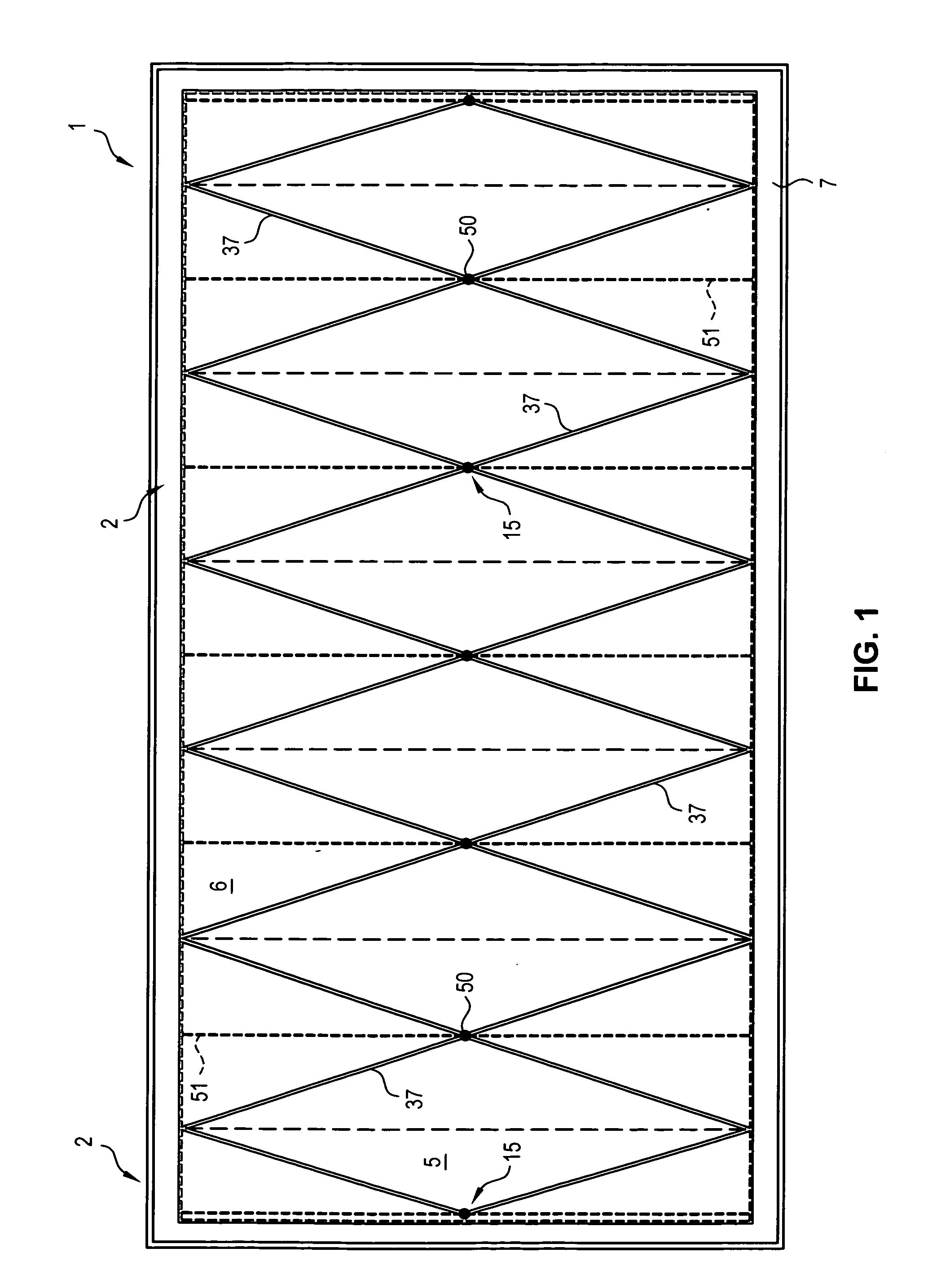
[0042]FIG. 1 illustrates a site incorporating the fluid containment and management system of the present invention. In the illustrated example, the site is a well pad 1 which is typically used for the extraction of natural gas from shale using a “pressurized fracturing” process, which is commonly referred to as “fracking”. It is to be understood, however, that the illustrated well pad 1 is only one example of any of a number of implementations that can make use of the fluid containment and management system of the present invention. For example, the illustrated well pad 1 is generally rectangular, having an area on the order of 180,000 square feet, which is typical for a fracking operation. Nevertheless, both the shape and the size of the well pad 1 can be varied to suit a particular application, location or operating environment, as desired. Variations are also possible to accommodate use of the well pad 1 for other types of drilling operations, in any of a variety of fields other ...


PUM


Abstract

A system for containing and managing fluids produced at a work site, such as an oil or gas drilling site, includes one or more fluid containments formed as a basin for collecting and retaining fluids, a berm forming a perimeter of the containments, a layer of sand placed over each basin, a fluid-impermeable membrane placed over the layer of sand, and drainage stone placed over the membrane, filling the basin. A geotextile fabric can be placed over the membrane to help protect the membrane from adverse affects of the drainage stone. A leak detection system can be coupled with the membrane to identify potential leaks in a containment system. One or more catch basins can extend through the basin and the drainage stone filling the basin, to receive fluids. A drainage system is placed in fluid communication with the catch basins to drain fluids from a containment.

Description

BACKGROUND OF THE INVENTION[0001]The present invention generally relates to a system for the effective containment of fluids, primarily precipitation and effluent arising from operations at a given site, and for management of the contained fluids. The system is particularly well suited to sites intended for gas and oil well drilling, but is also useful with sites for performing other functions that can benefit from improved fluid containment and management, including water, sewage and storm water systems.[0002]There are currently no consistent regulatory standards, from state to state, governing the construction of environmental protection systems used in the oil and gas exploration and extraction industries. About 80% of states require a raised dike system around storage tanks for produced water and separator tanks for receiving oil, gas and produced water. Some, but not all states require impermeable liners within the dikes. Fluid storage basins are also used for the temporary sto...

Claims


Application Information

Patent Timeline
Patent Type & Authority Applications(United States)
IPC IPC(8): B65G5/00
CPCF17D1/08B65G5/00Y10T137/8593
Inventor NOLT, DAVID A.
Owner D A NOLT
Why Eureka
Try Eureka