Battery pack having cooling system

a battery pack and cooling system technology, applied in the direction of battery/fuel cell control arrangement, cell components, propulsion by batteries/cells, etc., can solve the problems of large amount of heat generated by unit cells, temperature inside unit cells to increase, unit cells degraded, etc., and achieve the effect of speeding up heat conduction

Active Publication Date: 2013-04-11
GO TECH ENERGY
View PDF2 Cites 5 Cited by
  • Summary
  • Abstract
  • Description
  • Claims
  • Application Information

AI Technical Summary

Benefits of technology

[0019]Preferably, the battery pack further includes a circulating system providing cooling liquid passing through the hollow portion of the thermal conducting bar from one end to the other for speeding up heat conduction.

Problems solved by technology

In such a high-output, large-capacity battery pack, however, a large amount of heat is generated from the unit cells during the charge and the discharge of the unit cells.
When the heat generated from the unit cells during the charge and the discharge of the unit cells is not effectively removed, heat is accumulated in the unit cells with the result that the unit cells are degraded.
The heat generated at the unit cells may also cause the temperature inside the unit cells to increase, resulting in explosion thereof.
Since a battery module for a HEY is charged and discharged by a high current, it may have deteriorated performance due to the heat generated by the internal reaction of a rechargeable battery.
However, the intervals between the unit cells 11 can't be too small or else the coolant won't be able to circulate, and therefore, the size of the rechargeable battery module 10 is limited and can't be minimized.
However, such structure makes the battery bulgy which is not suitable for compact designs of battery packs.

Method used


Image

  • Battery pack having cooling system
  • Battery pack having cooling system
  • Battery pack having cooling system

Examples


first embodiment

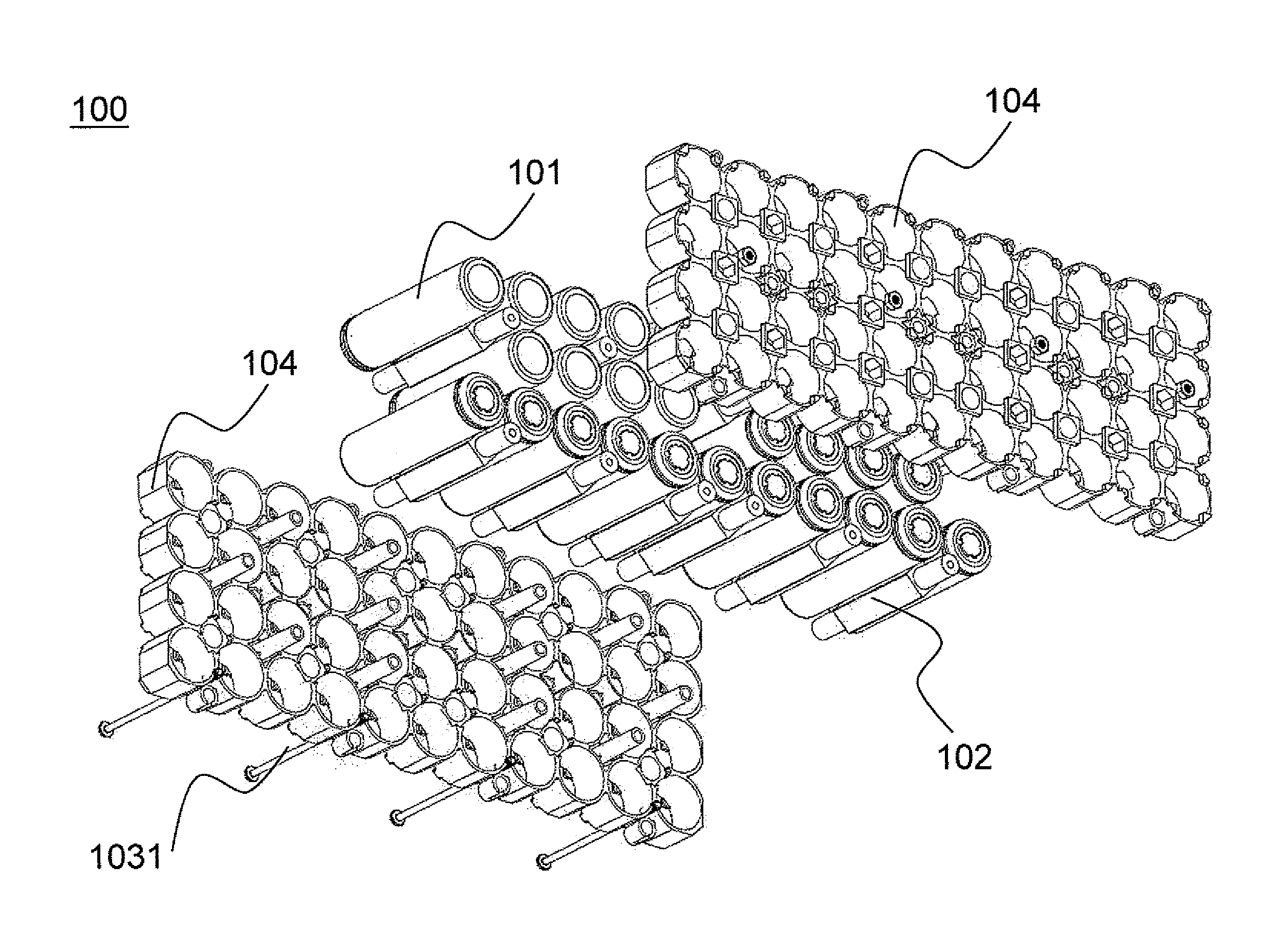
[0039]Please refer to FIGS. 3 to 5. A first embodiment is illustrated. Please refer to FIG. 3. It shows an appearance of a housing 103 of a battery pack 100. As shown, there are many screws 1031 on the housing 103. Functions of the screws 1031 will be described later in this embodiment.

[0040]Next, please refer to FIG. 4. It is an explosion diagram of the battery pack 100 without the housing 103. The battery pack 100 has a number of battery units 101, a number of thermal conducting bars 102 and two fixtures 104. The battery units 101 are linked in series or in parallel and arranged in a plane. They are the basic units to provide power. In order to have a comprehensive understanding of the thermal conducting bar 102, please refer to FIG. 5. The thermal conducting bar 102 has four side walls 1025 and two ends 1021. Please refer to FIGS. 4 and 5 at the same time. The thermal conducting bar 102 is averagely located among the battery units 101 and substantially contacted to the battery un...

second embodiment

[0044]In the first embodiment, the thermal conducting bar 102 is a solid element and just has two ends 1021 drilled for screwing. According to the spirits of the present invention, the thermal conducting bar 102 can be hollow.

[0045]Please refer to FIG. 6. A second embodiment is illustrated. There are many elements identical between the first and second embodiments. Those elements have the same functions. The only difference is in the thermal conducting bar 102. The thermal conducting bar 102 in the second embodiment is hollow. Therefore, a channel 1026 (although not seen but shown in dashed lines) is formed through the thermal conducting bar 102. A pump 1027 and two pipes 1028 and 1029 form a circulating system. The circulating system provides cooling liquid passing through the channel 1026 of the thermal conducting bar 102 from one end 1021 to the other. Thus, heat conduction can speed up. Water is used for the cooling liquid and follows the circulation direction shown in a solid a...

third embodiment

[0047]Please refer to FIG. 7 and FIG. 8. A third embodiment is illustrated. According to the present invention, the number of side walls 1025 equals the number of battery units 101 surrounding the thermal conducting bar 102 mentioned in the first embodiment. The side wall 1025 is substantially the same as a portion of battery unit 101 which contacts the thermal conducting bar 102.

[0048]Members having like functions will be identified by the same reference numerals and overlapping descriptions will be omitted. Please refer to FIG. 7 which illustrates a cross sectional view of the thermal conducting bar 102 and the battery units 101 thereof surrounded. In the first embodiment, the thermal conducting bar 102 has a cross section of a square. In this embodiment, the thermal conducting bar 102 has a cross section of a hexagon which allows six battery units 101 to be contacted, The thermal conducting bar 102 is used to efficiently dissipate heat radiated from the battery units 101. The sha...


PUM

PropertyMeasurementUnit
conductingaaaaaaaaaa
thermal conductiveaaaaaaaaaa
thermal conductingaaaaaaaaaa

Abstract

A battery pack having a cooling system is disclosed. The battery pack includes battery units linked in series or in parallel and arranged in a plane; thermal conducting bars each has a number of side walls and two ends, averagely located among the battery units and substantially contacted to the battery units by the side walls, for conducting heat out of the battery units to the two ends; and a housing for containing the battery units and thermal conducting bars and conducting heat from the ends of the thermal conducting bars to outside of the housing. At least one end of the thermal conducting bar is connected to the housing and becomes an internal supporting structure of the housing.

Description

FIELD OF THE INVENTION[0001]The present invention relates to a battery pack. More particularly, the present invention relates to a battery pack having a cooling system to dissipate heat from the battery pack. It can be applied to huge power required host, such as an electric vehicle.BACKGROUND OF THE INVENTION[0002]An electric vehicle, also referred to as an electric drive vehicle, is a moving vehicle using one or more electric motors as driving system. Not like petroleum-based transportations which are moved by the energy from burning gasoline, the electric vehicles use electric power as their propulsion. They won't generate waste gas. Noise is also less. During the last few decades, increased concern over the environmental impact of the petroleum-based transportation, along with the spectre of peak oil, has led to renewed interest in an electric transportation. Electric power for electric vehicles can be generated from a wide range of sources, including fossil fuels, nuclear power...

Claims


Application Information

Patent Timeline
Patent Type & Authority Applications(United States)
IPC IPC(8): H01M10/50H01M50/213H01M50/244H01M50/262H01M50/264
CPCH01M2/0237H01M2/1077H01M10/5004H01M10/503H01M10/5055B60L11/1879H01M10/5075Y02T10/7005Y02T10/7061B60L11/1864B60L11/1874H01M10/5059H01M10/6557H01M10/6567H01M10/6555H01M10/643H01M10/613B60L58/21B60L58/26B60L50/64Y02T10/70Y02E60/10H01M50/213H01M50/264H01M50/262H01M50/244
Inventor SOONG, TZU WENCHIEH, HSUN HAO
Owner GO TECH ENERGY
Why Eureka
Try Eureka