Drive device for hybrid electric vehicle
a hybrid electric vehicle and drive device technology, applied in vehicle sub-unit features, transportation and packaging, gearing, etc., can solve the problem of not being able to drive the hybrid electric vehicle, and achieve the effect of reducing the capacity of m/gs, reducing manufacturing costs, weight and siz
- Summary
- Abstract
- Description
- Claims
- Application Information
AI Technical Summary
Benefits of technology
Problems solved by technology
Method used
Image

Examples
first embodiment
[0071]The operation of the drive device of the first embodiment will be described with reference to an operation table shown in FIG. 5.
[0072]In the operation table in FIG. 5, running modes and driving modes are assigned in the columns of the table, while engaging elements such as the brake and the clutch and M / Gs are assigned in the rows of the table.
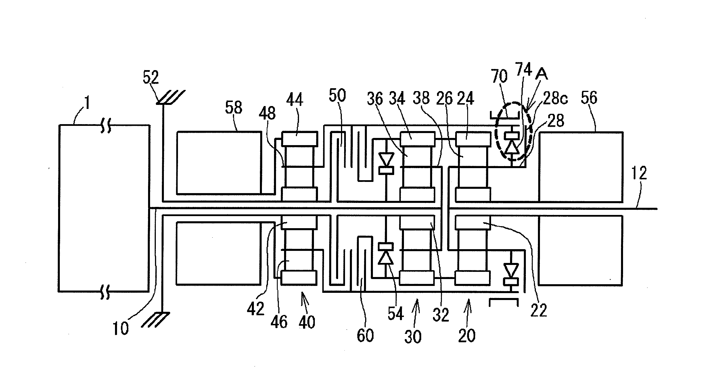
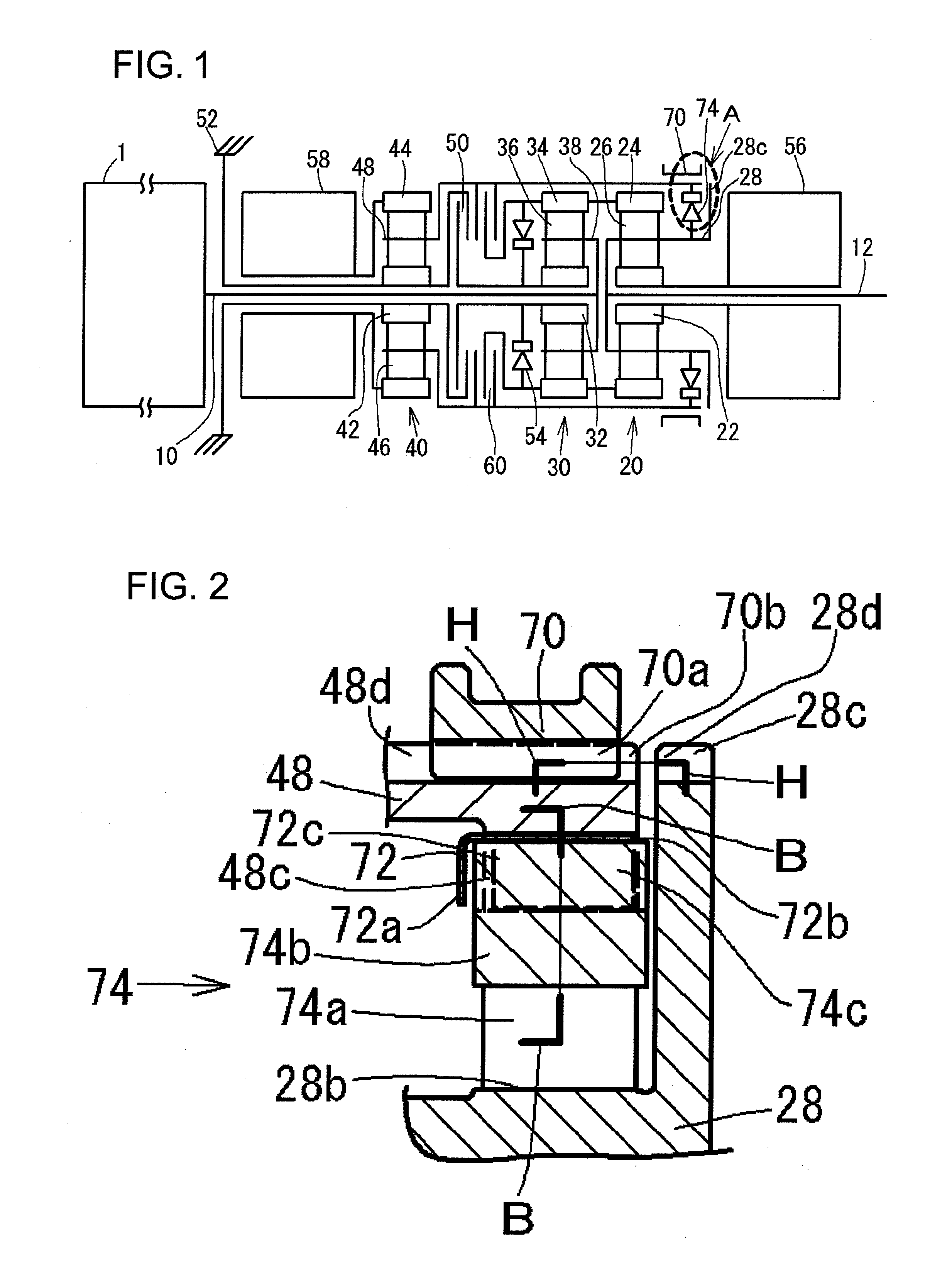
[0073]In the table the clutch 60 is denoted as “C”, the brake 50 is denoted as “B”, the sleeve 70 is denoted as “S”, the first overrunning clutch 54 is denoted as “OWC1”, the second overrunning clutch 74 is denoted as “OWC2”, the first M / C 56 is denoted as “MG1”, and the second M / G 58 is denoted as “M / G2”.
[0074]In the table, “0N” indicates the engagement of the corresponding engaging elements or the drive of the corresponding first or second M / G 56, 58, and “GE” indicates the generation of electric power by the corresponding first or second M / G 56, 58. In addition, “-” indicates a state where the corresponding M / G is stoppable.
[0075]Inc...
embodiment 40
[0163]The connection relationship of the third planetary embodiment 40, which functions as a reduction gear set, is set as described above, the reduction speed ratio between the second M / G 58 and the output shaft 12 can be set wider. Therefore, the torque when the vehicle starts can be set large.
third embodiment
[0164]Next, the present invention will be described.
[0165]FIG. 10 shows a power train of a drive device for a hybrid electric vehicle of the third embodiment.
[0166]The third embodiment is different from the first embodiment in that the second planetary gear set 30 is removed and a connection relationship of a third planetary gear set 40 is similar to that of the second embodiment.
[0167]An input shaft 10 is connectable with a first ring gear 24 in one rotational direction (in a rotational direction of an engine 1) through a first overrunning clutch 54, and it is connectable with the first ring gear 24 in any rotational direction through a second clutch 68.
[0168]A first clutch 60 can connect the first ring gear 24 and a second M / G 58 with each other.
[0169]A second fixing device 52f is provided to fix the input shaft 10 on a case 52. Specifically, the input shaft 10 has dog teeth 10a, which is engageable with a second fixing arm 52g so that the input shaft 10 can be fixed.
[0170]The sec...
PUM
 Abstract
Description
Claims
Application Information
 - R&D
- Intellectual Property
- Life Sciences
- Materials
- Tech Scout
- Unparalleled Data Quality
- Higher Quality Content
- 60% Fewer Hallucinations
Browse by: Latest US Patents, China's latest patents, Technical Efficacy Thesaurus, Application Domain, Technology Topic, Popular Technical Reports.
© 2025 PatSnap. All rights reserved.Legal|Privacy policy|Modern Slavery Act Transparency Statement|Sitemap|About US| Contact US: help@patsnap.com