
Orbital, non-reciprocating, internal combustion engine

a technology of internal combustion engine and reciprocating piston, which is applied in the direction of machines/engines, liquid fuel feeders, mechanical apparatuses, etc., can solve the problems of side loading of the piston against the cylinder wall, frictional losses, and remain energy-consuming effects, and achieves improved engine efficiency and simplicity, low cost, and high strength

Active Publication Date: 2013-04-18
LOCKSHAW JAMES +1
View PDF2 Cites 3 Cited by
  • Summary
  • Abstract
  • Description
  • Claims
  • Application Information

AI Technical Summary

Benefits of technology

The CC engine is a new kind of engine that increases its leverage through the whole power stroke, resulting in high power at low engine speeds. It is simpler and more efficient than current designs, and can be powered by both liquid and gaseous fuels. The engine's lightness, low cost, and simplicity make it ideal for use as an electrical generator or power transfer device. It reduces friction, pumping, cooling, and vibration losses, and combustion efficiency is improved compared to current designs. Overall, the CC engine is a promising step forward in engine modernization.

Problems solved by technology

The connecting rod, traveling with the piston and articulating at the wrist pin and orbiting at the crankshaft presents a changing angular force that results in side loading of the piston against the cylinder wall.
This causes frictional losses.
Because of acceleration and deceleration of the piston components in their movements, the internal combustion reciprocating engine requires a flywheel to moderate these energy surges, but this is an imperfect solution and there remain energy-consuming effects.

Method used


Image

  • Orbital, non-reciprocating, internal combustion engine
  • Orbital, non-reciprocating, internal combustion engine
  • Orbital, non-reciprocating, internal combustion engine

Examples


Embodiment Construction

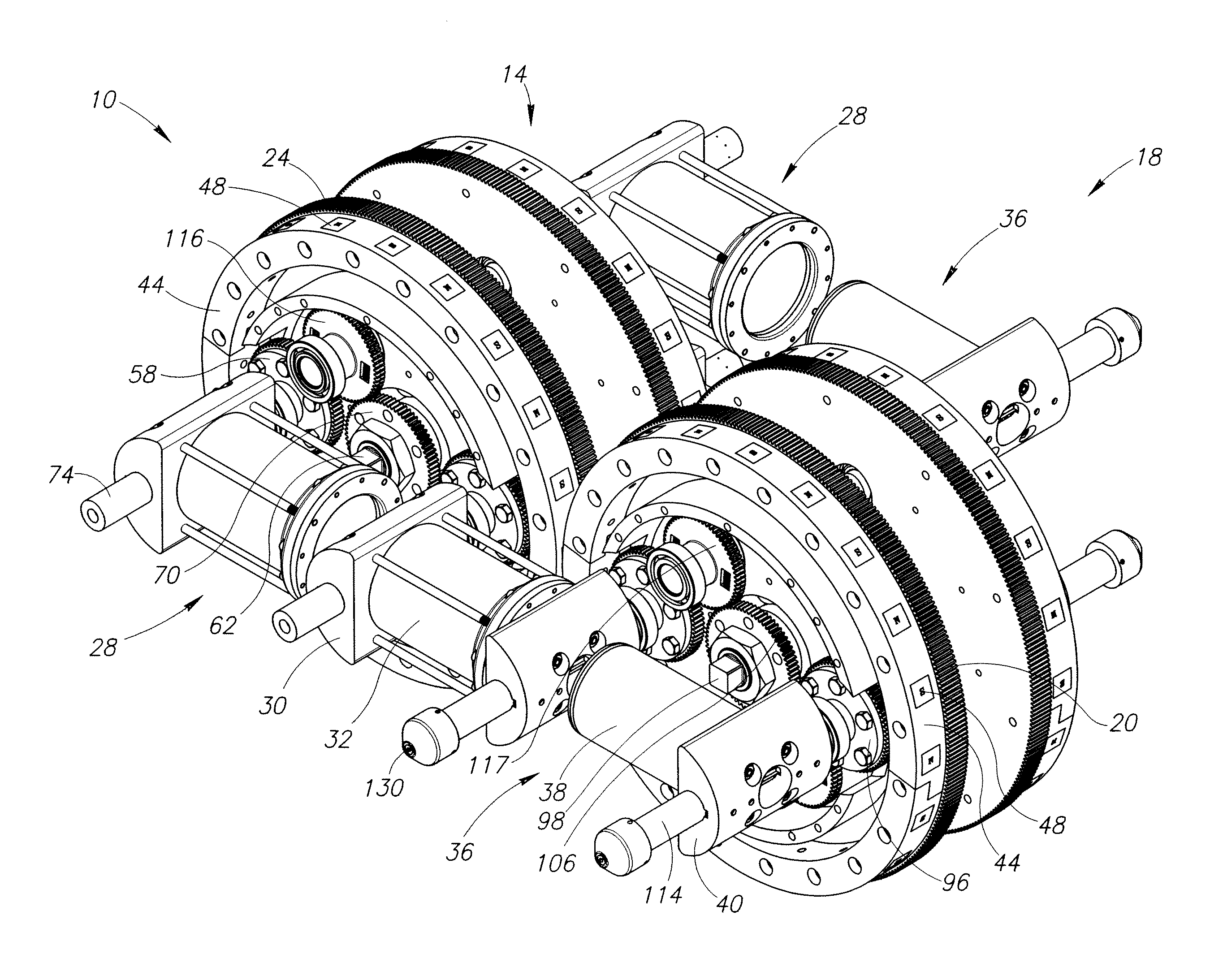
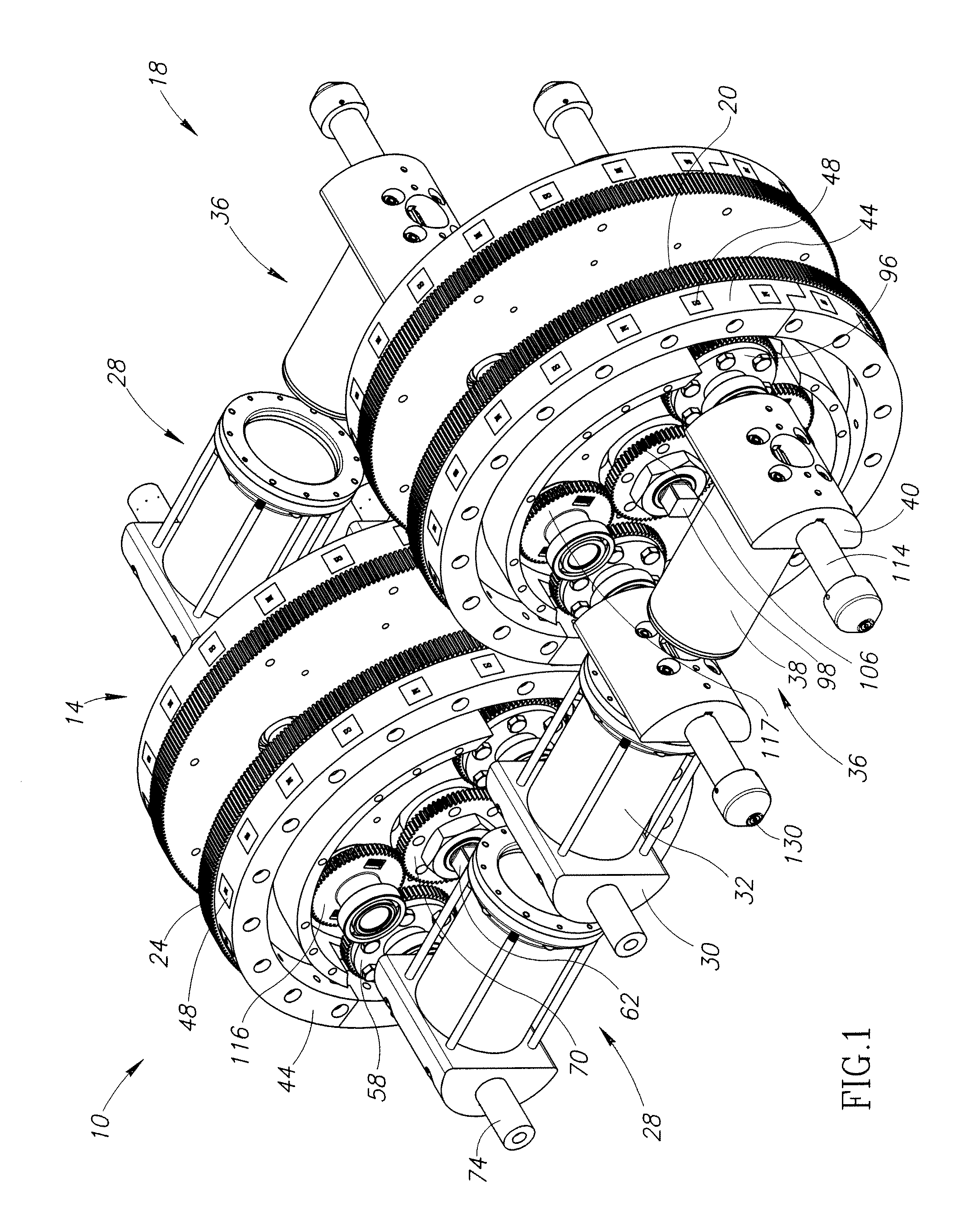
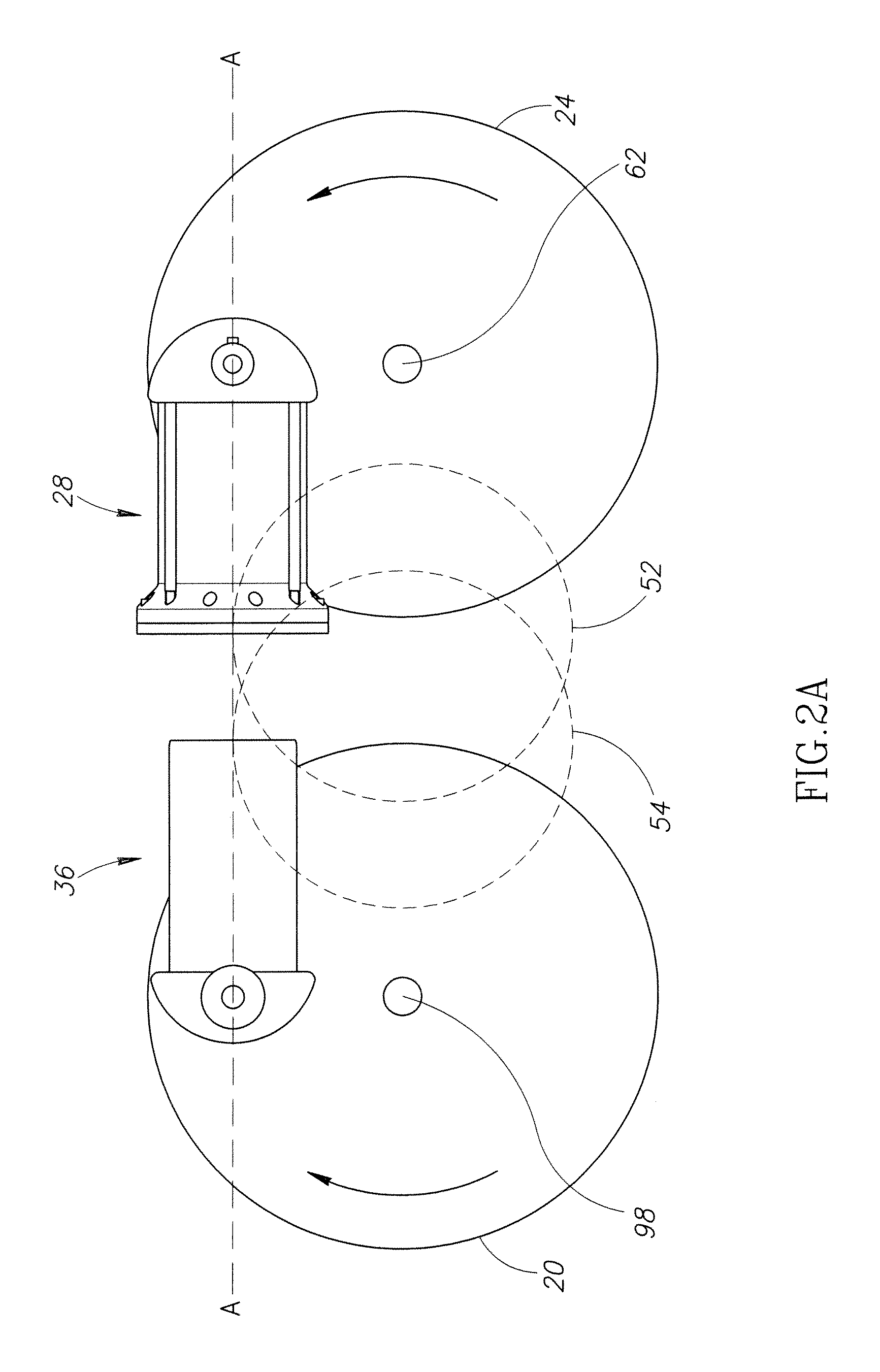
[0030]With reference now to the drawings in detail, and particularly FIG. 1, a piston drive wheel assembly 18 and a cylinder drive wheel assembly 14 for a combustible fluid-operated orbital engine 10 is shown. A fully assembled view of the engine 10 is shown in FIG. 13. The cylinder drive wheel assembly 14 comprises two substantially mirrored sets of two cylinders 28, and the piston drive wheel assembly 18 comprises two corresponding substantially mirrored sets of two pistons 36. The pistons 36 each comprise a piston head 40 coupled to a piston axle or shaft 114, and a piston body 38. The cylinders 28 each comprise a cylinder head 30 coupled to a cylinder axle or shaft 74, and a cylinder sleeve 32 configured for receiving a piston 36. Each of the pistons 36 are arranged so that they are at all times in opposed relation on a common longitudinal axis with a corresponding cylinder 28. As shown in FIGS. 2A-2D, the cylinders 28 and pistons 36 are configured for orbital motion along inter...


PUM


Abstract

A combustible fluid-operated orbital engine having sets of cooperating cylinder and piston members with respective parallel axes of rotation. Respective cylinder and piston carrier wheels with respective axes of rotation parallel to the piston / cylinder axes of rotation carrying the pistons / cylinders circularly and orbitally and at all times in opposed relation on a common longitudinal axis along intersecting counter paths. Respective gearing structures or belts / sprockets supported by the cylinder and piston carrier wheels rotate the pistons / cylinders counter to their circular motion direction to maintain their opposed relation for their periodic interfittment when their respective paths intersect. A combustible fluid supply is provided to the cylinder member for combustion coincident with the periodic interfittment in engine operating relation. The pistons / cylinders may include ceramic material. The compression sealing system is located in the entry of each cylinder rather than being connected to the piston.

Description

FIELD OF THE INVENTION[0001]Embodiments of the present invention relate generally to internal combustion engines, and more specifically, to orbital, non-reciprocating internal combustion engines.BACKGROUND OF THE INVENTION[0002]The Otto Cycle engine is a reciprocating internal combustion engine. Many of the key work-producing components of the Otto Cycle engine reciprocate, that is they are required to move in a first direction, stop, and then move in a second, opposite direction in order to complete the cycle. In the Otto Cycle engine, there are four changes of direction of the piston assembly in effecting a single power stroke. Piston assemblies (e.g., pistons, rings, wrist pins and connecting rods) travel up into their respective cylinders at a changing rate of speed to top dead center (i.e., to the end of the stroke), where they stop and then return down the cylinder to the bottom of the stroke. The connecting rod, traveling with the piston and articulating at the wrist pin and ...

Claims


Application Information

Patent Timeline
Patent Type & Authority Applications(United States)
IPC IPC(8): F02B53/02F02B53/12F02B53/00F02B53/10
CPCF02B59/00F02B57/00F02B57/06F02B57/02Y02T10/17F01B15/02F01B9/04
Inventor LOCKSHAW, JAMESGERONDALE, JOSEPH
Owner LOCKSHAW JAMES
Learn More