Fixed-wing and electric multi-rotor composite aircraft

a composite aircraft and electric multi-rotor technology, applied in the field of aircraft, can solve the problems of consuming more power, severely affecting the efficiency of the direct connection with the dynamic system, and affecting the performance of the fixed-wing aircraft in remote rural areas without dedicated airports

Inactive Publication Date: 2013-04-18
YUNEEC TECH CO LTD
View PDF15 Cites 67 Cited by
  • Summary
  • Abstract
  • Description
  • Claims
  • Application Information

AI Technical Summary

Problems solved by technology

The fixed-wing aircraft has high flying speed, long flying range and long cruise time; but it needs long distance to take off and land, and requires high quality runway; thus the application of the fixed-wing aircraft in remote rural area without dedicated airport is severely affected and obstructed.
Since the rotor connected directly with the dynamic system has much lower efficiency than the wing of the fixed-wing aircraft, it consumes more power.
Thus, the flying speed, the flying distance and the cruise time of the helicopter are not as good as those of the fixed-wing aircraft.
The lift engine itself has simple design, and yet it does not work when the aircraft cruises and it occupies space inside the aircraft, so the weight of the lift engine is dead weight.
It is an urgent problem for the vertical take-off and landing aircraft to decrease or eliminate the dead weight.
Firstly, the location of the engine in the aircraft is too limited if the engine is tilted, the location of the wing and the engine must accord to the center of gravity of the aircraft, and basically it can only be under the wing or at the wing tip.
Thus, if parts of the lift engines break down or generate insufficient energy instantly, the asymmetric lift can cause disastrous accident easily.
The tilting rotors use the synchronizing shaft to solve this problem, but the tilting jet engine nearly cannot be compensated by the engine on one side when the engine on the other side fails.
Secondly, the engine itself is very heavy, the tilting mechanism is difficult to realize.
Thirdly, the engine has a high requirement for the inlet, otherwise the engine efficiency plummets.
But when the engine is tilted, the condition of the inlet is hard to maintain.
Moreover, the vertical take-off and landing requires generating a large amount of thrust in a short time; the cruise requires long working hours but not so much thrust; it's hard to coordinate these two conditions in the design.
The lift is generated by the engines directly, no way to manipulate.
1. As shown in FIG. 1, it is a scheme which combines the ducted fan and the forward blade 11. For instance, the UAV Mariner of Sikorsky Aircraft Corporation, XV-5 of the General Electric Company, etc.. The disadvantage of this type of aircraft is that the duct adds some weight, increases more air drag and obstructs the arrangement of the load and equipments in the aircra

Method used


Image

  • Fixed-wing and electric multi-rotor composite aircraft
  • Fixed-wing and electric multi-rotor composite aircraft
  • Fixed-wing and electric multi-rotor composite aircraft

Examples


first embodiment

The first embodiment

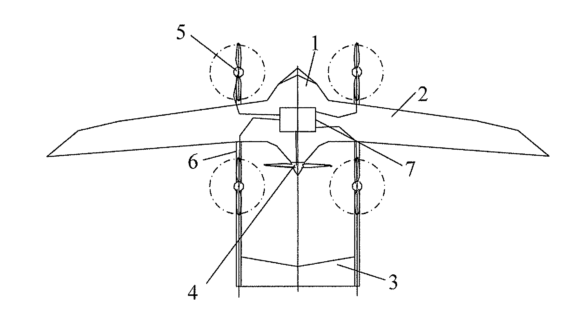
[0047]A fixed-wing and electric multi-rotor composite aircraft of the present invention as shown in FIG. 5 comprises a set of fixed-wing aircraft parts, which comprises airframe 1, main wing 2, tail 3 and fixed-wing dynamic system 4 (also named fixed-wing aircraft dynamic system), namely, the fixed-wing dynamic system 4 provides power to the fixed-wing aircraft parts. The persons skilled in the art shall understand that the main wing and the fixed-wing in the text refer to the same part; it is named the fixed-wing relative to the rotor; it is named the main wing relative to the tail according to the aircraft structure. On the basis of the fixed-wing aircraft parts, therein four sets of electric multi-rotor dynamic system 5 are added, which provides power to the rotor helicopter parts. But it is not limited to four sets. The electric multi-rotor dynamic system 5 can be realized by using the specific composition and structure of the existing helicopter, so no furth...

second embodiment

The Second Embodiment

[0069]As shown in FIGS. 14 and 15, the difference between this embodiment and the first embodiment lies mainly in: there are six sets of electric multi-rotor dynamic system in this embodiment, therein four sets are installed on the main wing, and the other two sets are installed at the location near the tail on the airframe. As shown in FIG. 15, a jet apparatus 8 is installed at the aircraft tail, and the exhaust air can be used as power to propel the aircraft to fly forward. The rest parts are basically the same as in the first embodiment.


PUM


Abstract

The present invention discloses a fixed-wing and electric multi-rotor composite aircraft, including an electric multi-rotor dynamic system and a main controller, the fixed-wing dynamic system and electric multi-rotor dynamic system are mutually independent structurally, the main controller includes the fixed-wing control system and an electric multi-rotor control system which is used for controlling the operation of the electric multi-rotor dynamic system, the main controller is also used for controlling the fixed-wing control system and the electric multi-rotor control system to operate independently or synergistically, the rotor rotating plane of the electric multi-rotor dynamic system is parallel to the airframe central shaft. The aircraft is able to shift between two flying modes freely, and takes off, lands and flies like a helicopter as well as a fixed-wing aircraft. A fixed-wing aircraft-helicopter mixed mode can also be used in the take-off, landing and flying process.

Description

FIELD OF INVENTION[0001]The present invention relates to an aircraft, and more particularly relates to a fixed-wing and electric multi-rotor composite aircraft.DESCRIPTION OF RELATED ARTS[0002]For the common fixed-wing aircraft in the field of aviation, since it mainly uses the lift generated by the wing to balance the weight of the aircraft and the dynamic system is mainly used to overcome the drag of the aircraft, the fixed-wing aircraft can take off under the power (thrust) much smaller than the weight of the aircraft. The fixed-wing aircraft has high flying speed, long flying range and long cruise time; but it needs long distance to take off and land, and requires high quality runway; thus the application of the fixed-wing aircraft in remote rural area without dedicated airport is severely affected and obstructed.[0003]For the common rotor helicopter in the field of aviation, the problem to take off and land in a narrow space can be solved. Among known rotorcrafts, apart from co...

Claims


Application Information

Patent Timeline
IPC IPC(8): B64C27/26
CPCB64C27/26B64C29/0025B64C39/04Y02T50/12B64C39/12B64D27/24Y02T50/62B64C39/10Y02T50/10Y02T50/60
Inventor TIAN, YUJIANG, WENYAN
Owner YUNEEC TECH CO LTD
Why Eureka
Try Eureka