Method and system estimating rotor angle of an electric machine

a technology of rotor angle and system, which is applied in the direction of electronic commutators, motor/generator/converter stoppers, dynamo-electric converter control, etc., can solve the problems of difficult to accurately estimate with the application of conventional methods, inconvenient first approach for estimating rotor position, and error in estimating rotor position

Active Publication Date: 2013-04-18
DEERE & CO
View PDF4 Cites 16 Cited by
  • Summary
  • Abstract
  • Description
  • Claims
  • Application Information

AI Technical Summary

Benefits of technology

[0006]In one embodiment, a method and system for estimating rotor angle of an electric machine receives position samples from an encoder coupled to a permanent magnet electric machine. The position samples are stored in a data storage device. A data processor determines a first plurality of first changes in position (e.g., ΔP1) between successive position samples. A data processor determines a second plurality of second changes (e.g., ΔP2) between successive first changes in position. A data processor determines whether each first change in position (e.g., ΔP1) is generally increasing, decreasing or constant. A corrective motion factor (e.g., speed factor (ΔP1*n)+acceleration factor (ΔP2*m)) is applied to each stored position sample based on whether the first change in position is generally increasing or decreasing. The data processor estimates a final rotor angle of the electric machine based on a particular one of the position samples and a corresponding first change in position associated with the particular one of the position samples corresponding to a respective time.

Problems solved by technology

The electric machine may have a rotor angle or rotor position that is difficult to estimate accurately with the application of conventional approaches.
However, the first approach is not suitable for estimating the rotor position if the motor is operating at low rotational speeds because the back-EMF voltages are frequently too low to be accurately detected at low rotational speeds below a speed threshold (e.g., 100 revolutions per minute).
In addition, electromagnetic noise or interference from switching transients in one or more current-carrying phases of the electric machine can lead to error in estimates of rotor position.
The second approach is often computationally intensive and susceptible to quantification errors, truncation errors, and measurement inaccuracies.
The rotor position estimate of the second approach may be inaccurate when the motor is operating at low speeds below a speed threshold (e.g., 100 revolutions per minute (RPM)) because of the drift of integration functions, for example.
To be sufficiently accurate, the second approach generally needs to compensate for changes in motor parameters associated with temperature change, which contributes to the complexity of the computations.
Although the third approach works at low rotational speeds of the motor and is generally independent of rotor speed, the third technique cannot be used with non-salient permanent magnet motors, such surface mount, permanent magnet alternating current motors without rotor saliency.

Method used


Image

  • Method and system estimating rotor angle of an electric machine
  • Method and system estimating rotor angle of an electric machine
  • Method and system estimating rotor angle of an electric machine

Examples


Embodiment Construction

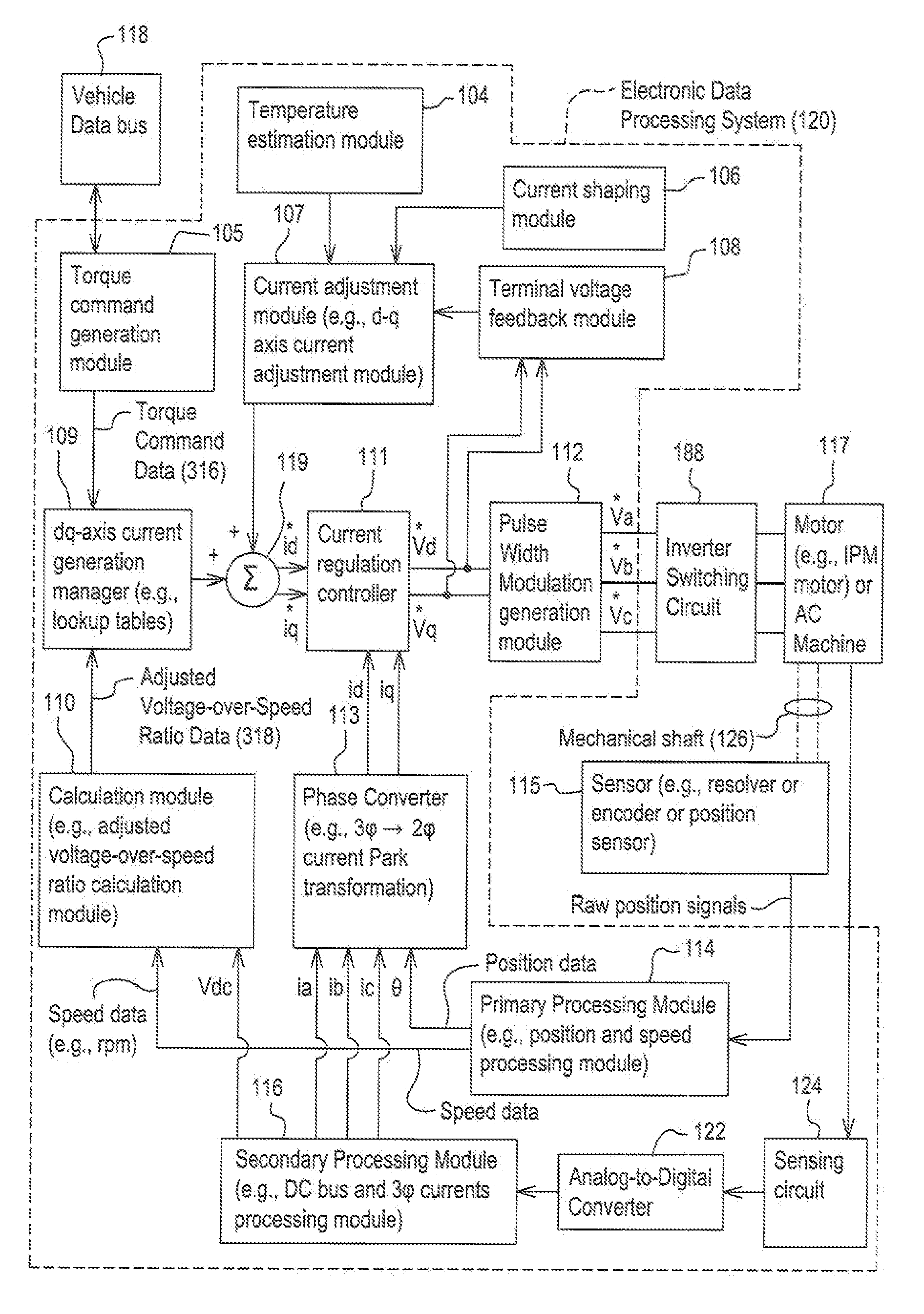
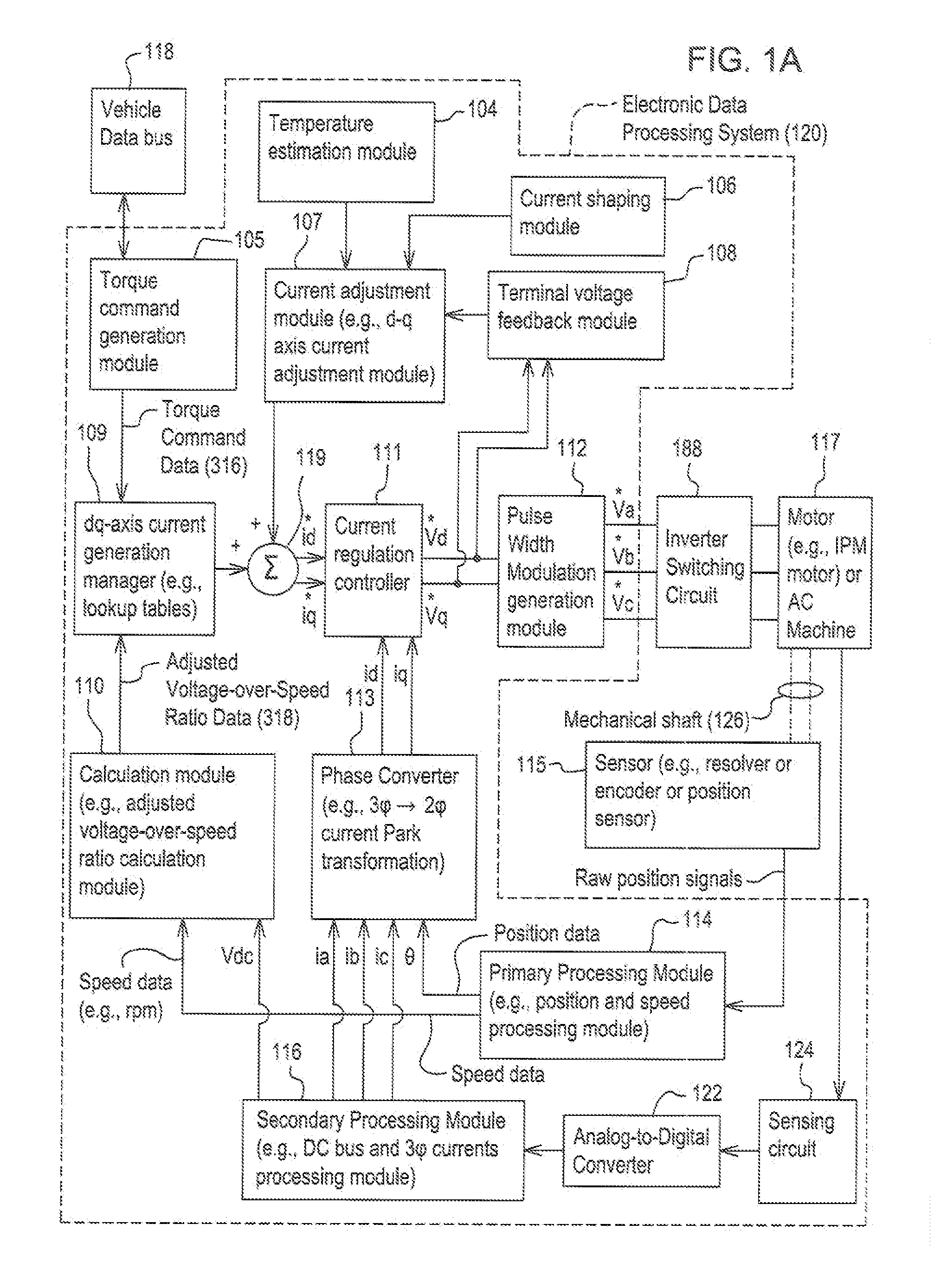
[0014]In accordance with one embodiment, FIG. 1A discloses system for controlling a motor 117 (e.g., an interior permanent magnet (IPM) motor) or another alternating current electric machine. In one embodiment, the system, aside from the motor 117, may be referred to as an inverter or a motor controller.

[0015]The system comprises electronic modules, software modules, or both. In one embodiment, the motor controller comprises an electronic data processing system 120 to support storing, processing or execution of software instructions of one or more software modules. The electronic data processing system 120 is indicated by the dashed lines in FIG. 1A and is shown in greater detail in FIG. 2.

[0016]The data processing system 120 is coupled to an inverter circuit 188. The inverter circuit 188 comprises a semiconductor drive circuit that drives or controls switching semiconductors (e.g., insulated gate bipolar transistors (IGBT) or other power transistors) to output control signals for t...


PUM


Abstract

Position samples are stored from an encoder coupled to a permanent magnet electric machine. A data processor determines first changes in position between successive position samples and second changes between successive first changes in position. A data processor determines whether each first change in position is generally increasing, decreasing or constant. A corrective motion factor is applied to each stored position sample based on whether the first change in position is generally increasing or decreasing. The data processor estimates a final rotor angle of the electric machine based on a particular one of the position samples and a corresponding first change in position associated with the particular one of the position samples corresponding to a respective time.

Description

FIELD OF THE INVENTION[0001]This invention relates to a method and system for estimating rotor angle or rotor position of an electric machine.BACKGROUND OF THE INVENTION[0002]An electric machine or electric motor may feature a rotor with permanent magnets and a stator. For example, the electric machine may comprise a permanent magnet (PM) motor, an interior permanent magnet (IPM) motor, or IPM synchronous motor. The electric machine may have a rotor angle or rotor position that is difficult to estimate accurately with the application of conventional approaches.[0003]There are several different conventional technical approaches for estimating an initial rotor position of an electric machine. Under a first approach, because the back-electromotive force (back-EMF) voltages of a motor are functions of the rotor position with respect to the stator, a sensor may extract rotor position information from the back-EMP waveform of an unexcited phase of a multi-phase alternating current motor. ...

Claims


Application Information

Patent Timeline
Patent Type & Authority Applications(United States)
IPC IPC(8): H02P6/16
CPCH02P6/001H02P6/06H02P21/146H02P6/34H02P21/18
Inventor THYAGARAJAN, LAV
Owner DEERE & CO
Why Eureka
Try Eureka