Image-capturing device

Inactive Publication Date: 2013-04-18
CANON KK
View PDF14 Cites 251 Cited by
  • Summary
  • Abstract
  • Description
  • Claims
  • Application Information

AI Technical Summary

Benefits of technology

[0008]According to the present invention, susceptibility to the amount of noise and exposure time

Problems solved by technology

However, providing a zoom optical system to each and every small camera is very expensive.
In this occasion, there is a problem that brightness or amount of noise differs among angles of view when photographs are taken by matching an exposure time regardless of the angle of view.
In addition, if an exposure time is chan

Method used


Image

  • Image-capturing device
  • Image-capturing device
  • Image-capturing device

Examples


first embodiment

[0031]First, the outline of an Embodiment 1 will be described. The Embodiment 1 relates to adjusting the balance of brightness of image data for respective angles of view captured by each image-capturing unit by providing a larger number of telescopic image-capturing units than wide-angle image-capturing units, for example.

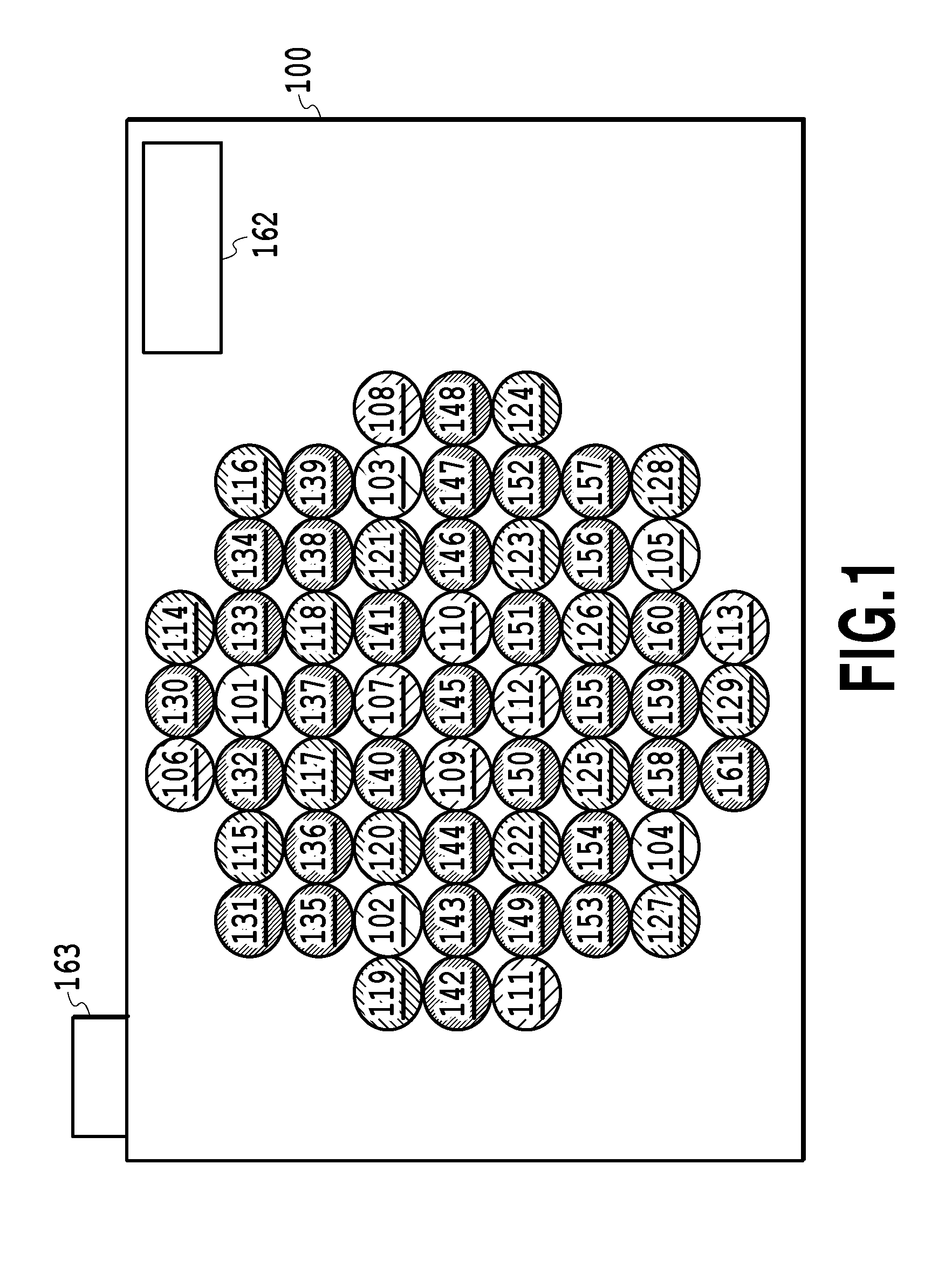
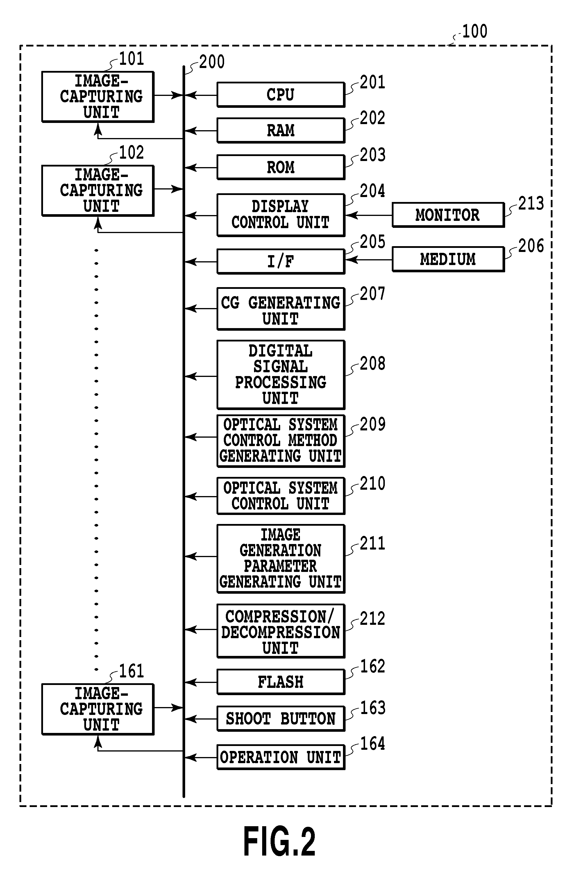
[0032]FIG. 1 shows a general appearance of an image-capturing device 100 of the Embodiment 1. The image-capturing device 100 shown in FIG. 1 is a so-called camera array (as known as camera array system, multiple lens camera, and the like) having 61 image-capturing units 101 to 161 on the front side (subject side). Different hatchings of the image-capturing units 101 to 161 shown in FIG. 1 indicate difference of angles of view as described below. The image-capturing device 100 further has a flash 162 and a shoot button 163. In addition, the image-capturing device 100 has an operation unit and a display unit or the like on its back side, although not shown in FIG. 1...

embodiment 2

[0080]In the case of the Embodiment 1, a configuration has been described in which all the sizes of entrance pupils of respective image-capturing units approximately coincide with each other. For the present embodiment, a configuration will be described in which sizes of entrance pupils of respective image-capturing units are different from each other. Description of parts that are common with the Embodiment 1 will be omitted.

[0081]FIG. 8 shows an exemplary appearance of an image-capturing device 800 of the Embodiment 2. The image-capturing device 800 is a so-called camera array having 16 image-capturing units 801 to 816 on the front side (subject side). The image-capturing device 800 has a flash 162 and the shoot button 163. In addition, although not shown in FIG. 8, the image-capturing device 800 has an operation unit, a display unit, or the like on the back side. Although a case will be described below for the embodiment having 16 image-capturing units, two or more image-capturin...

embodiment 3

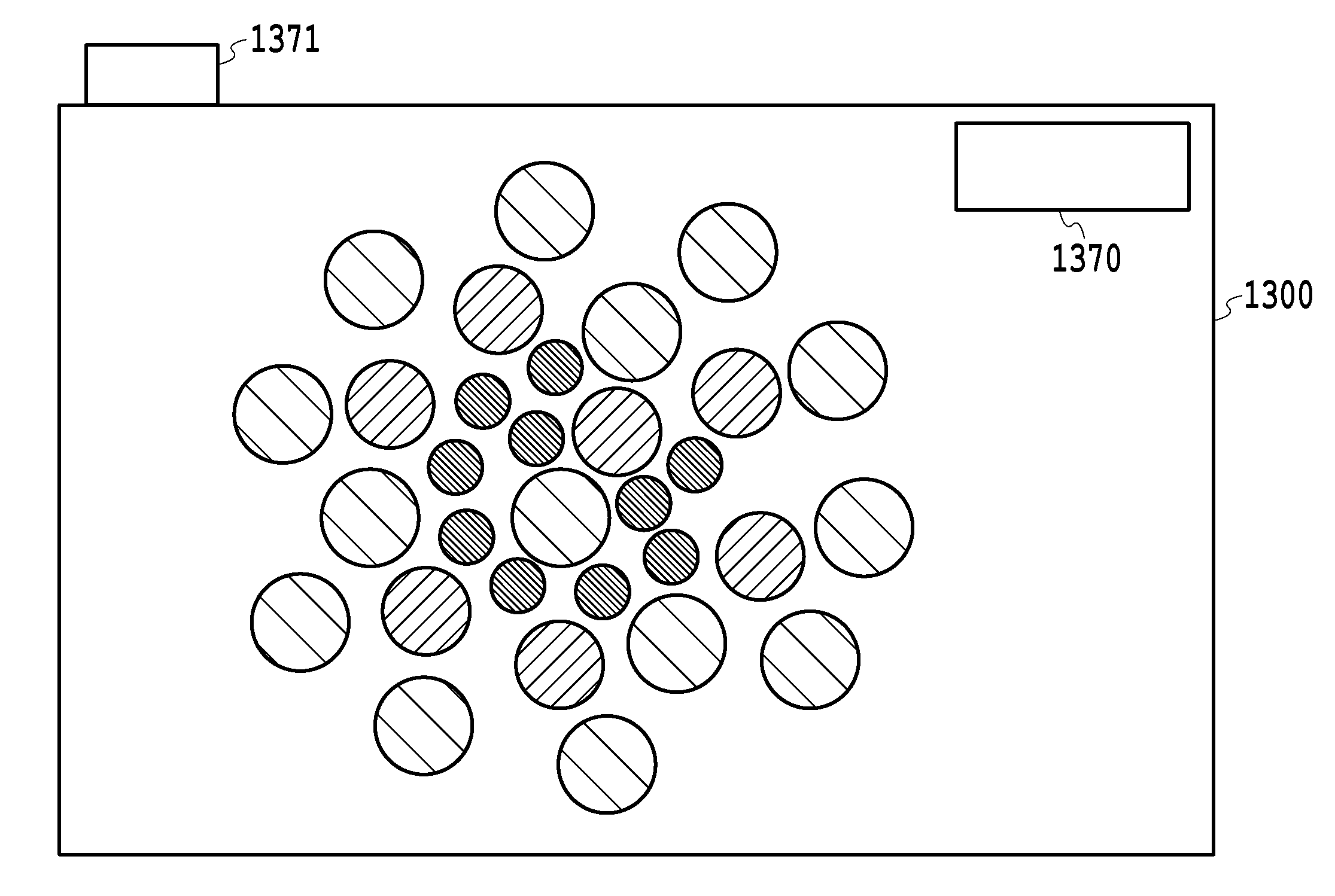
[0097]In the Embodiments 1 and 2, an example has been described for a case in which there are two or more types of angles of view for each image-capturing unit and one or more image-capturing units for each angle of view, and a plurality of captured data having a same angle of view are used at the time of image synthesis. In the Embodiment 3, a configuration will be described for a case where a plurality of captured data having different angles of view is used at the time of image synthesis.

[0098]FIG. 11 shows an exemplary appearance of an image-capturing device 1100 in the Embodiment 3. The image-capturing device 1100 is a so-called camera array having 18 image-capturing units 1101 to 1118 on the front (subject side). The image-capturing device 1100 has the flash 162 and the shoot button 163. As with the Embodiments 1 and 2, the image-capturing device 1100 has an operation unit or display unit on the back side. Although a case will be described below for the present embodiment havi...


PUM


Abstract

If a zoom magnification ratio of the image is changed after shooting, it is impossible to match brightness, amount of noise, exposure time between angles of view due to difference in light gathering ability of a camera. The number of one or more image-capturing units (130 to 161) having a first angle of view, among the plurality of image-capturing units, is made larger than the number of one or more image-capturing units (101 to 105) having a wider angle of view than the first angle of view. In addition, the amount of light being received in total by one or more image-capturing units (130 to 161) having a first angle of view is made approximately equal to the amount of light being received in total by one or more image-capturing units (101 to 105) having a second angle of view.

Description

BACKGROUND OF THE INVENTION[0001]1. Field of the Invention[0002]The present invention relates to an image-capturing device having a plurality of image-capturing units.[0003]2. Description of the Related Art[0004]There is proposed a method of changing, after taking a photograph, focus, diaphragm, zoom magnification ratio, or the like of the photographic image. For example, “High performance imaging using large camera arrays”, ACM Transactions on Graphics—Proceedings of ACM SIGGRAPH 2005, discloses a technique of generating, from image data captured by a multiple camera including a plurality of small cameras having a deep depth of field, image data having a shallower depth of field.[0005]When performing a zooming process in such a multiple camera, the simplest way is to provide individual small cameras with zoom optical systems, respectively. However, providing a zoom optical system to each and every small camera is very expensive. On the other hand, Japanese Patent Laid-Open No. 2005...

Claims


Application Information

Patent Timeline
IPC IPC(8): H04N7/00G03B19/07
CPCH04N5/23238H04N5/243H04N5/23296H04N23/698H04N23/69H04N23/76
Inventor YAHATA, KAZUHIRO
Owner CANON KK
Why Eureka
Try Eureka