
Optical coherence tomography and method thereof

a coherence tomography and optical coherence technology, applied in the field of optical coherence tomography and control method thereof, can solve the problem of long comparison time of acquiring images with a three-dimensional structure, and achieve the effect of high accuracy

Inactive Publication Date: 2013-04-18
CANON KK
View PDF2 Cites 13 Cited by
  • Summary
  • Abstract
  • Description
  • Claims
  • Application Information

AI Technical Summary

Benefits of technology

The present invention provides a better way to get tomicing images of an eye using optical coherence tomography. It helps to correct any movement that may occur while getting the images by using multiple images that are generated using light interference. This makes it more accurate.

Problems solved by technology

However, the time for acquiring the image with a three-dimensional structure becomes long compared to that for acquiring one tomographic image because of shooting the images by scanning multiple tomographic images.

Method used


Image

  • Optical coherence tomography and method thereof
  • Optical coherence tomography and method thereof
  • Optical coherence tomography and method thereof

Examples


first embodiment

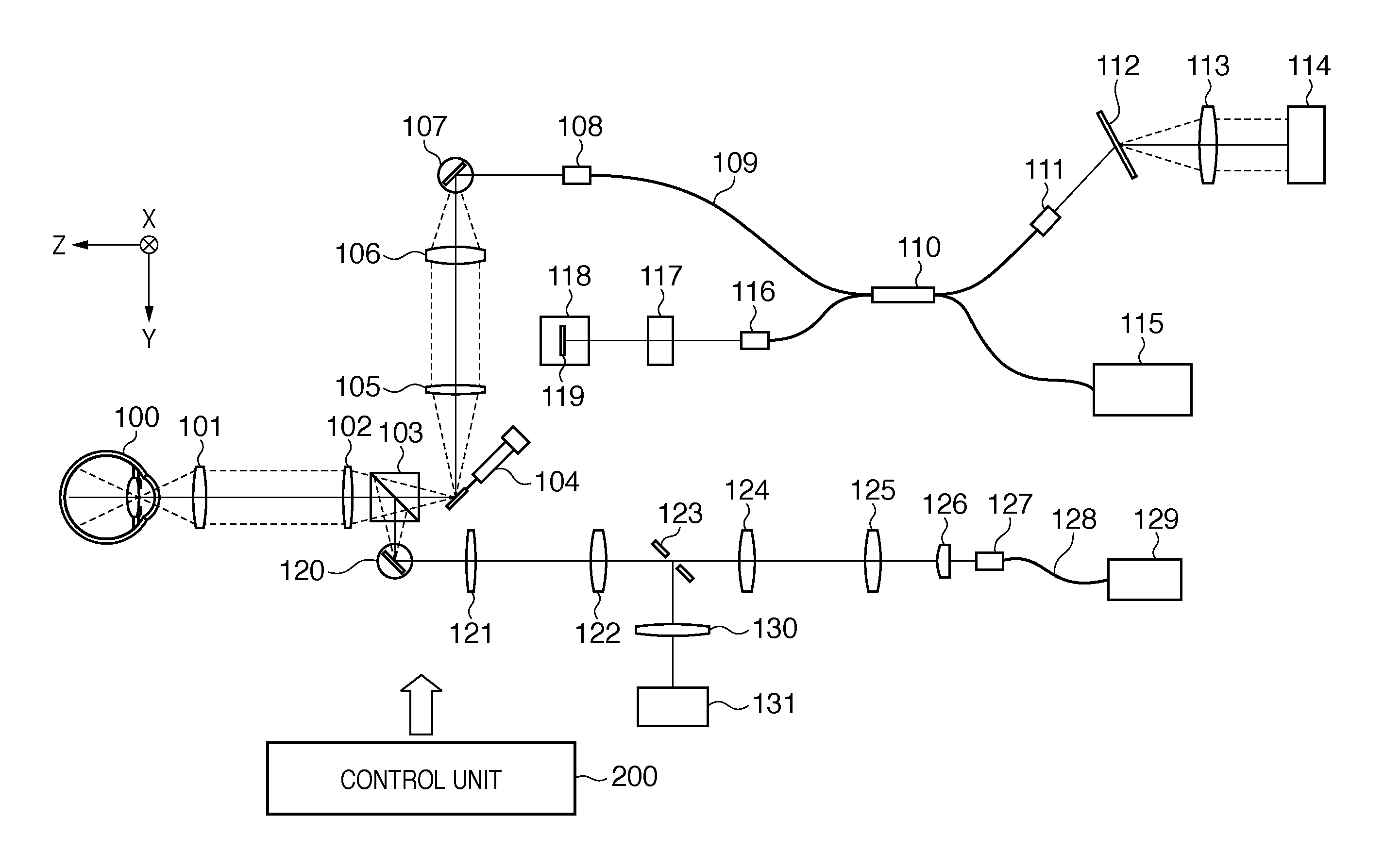
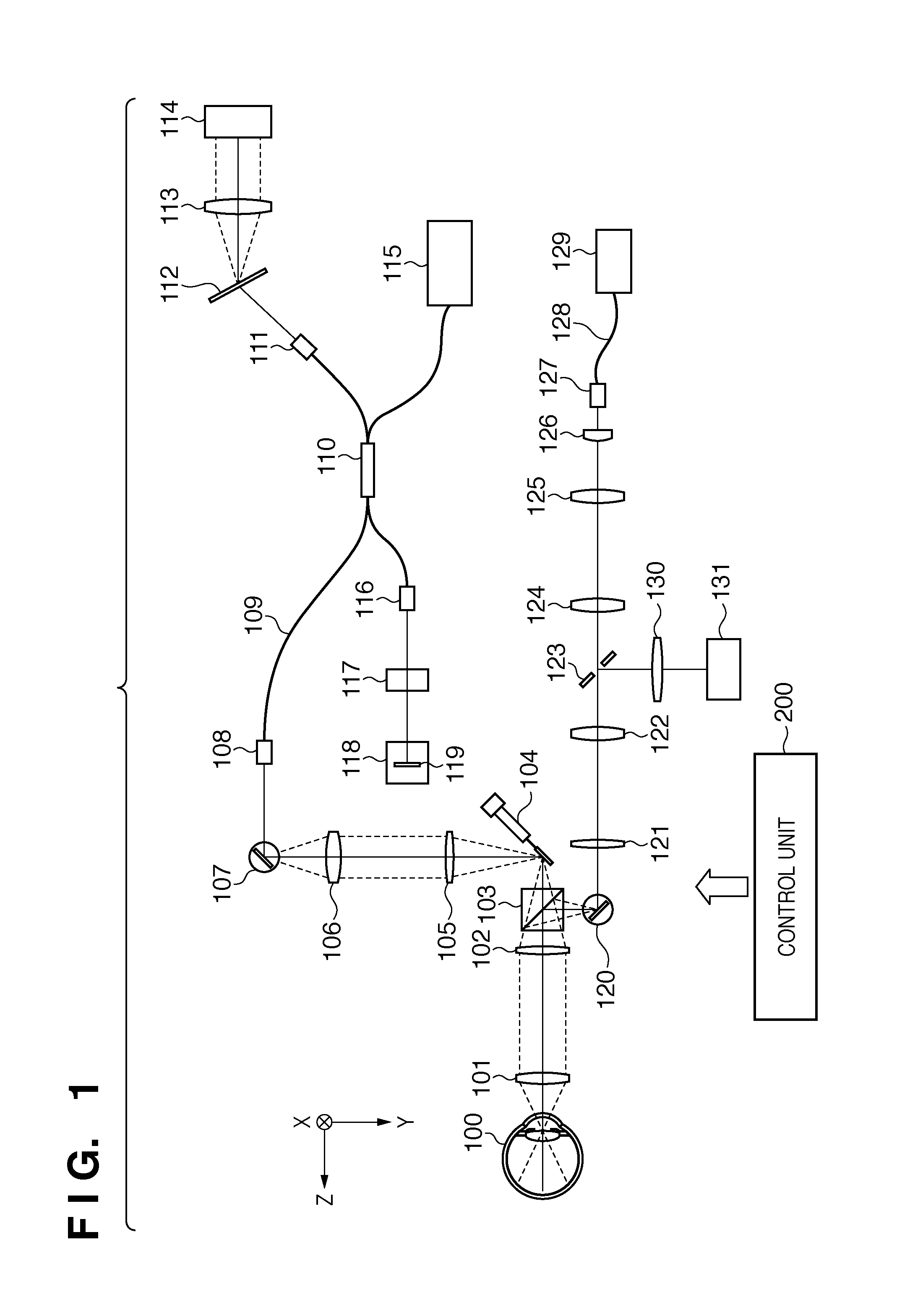
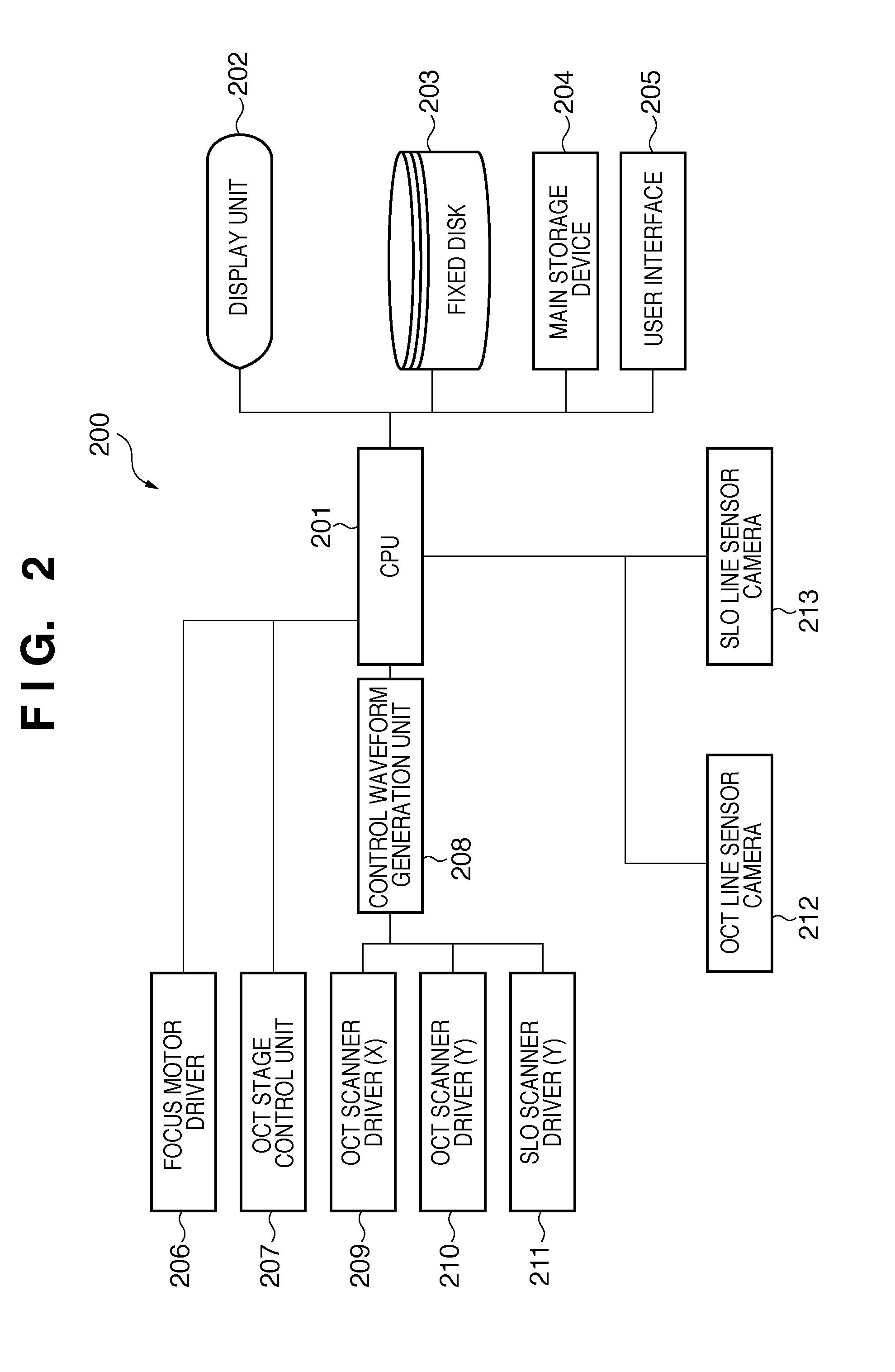
[0022]An image sensing apparatus in this embodiment comprises a first acquisition unit for acquiring multiple tomographic images by repeatedly moving its shooting position (topographic profile-position) of the topographic image along a first direction to a second direction, a second acquisition unit for acquiring a two dimensional fundus image and a control unit for controlling these units. In this embodiment, an OCT imaging unit is used as the first acquisition unit and SLO imaging unit is used as the second acquisition unit. Each element of the optical coherence tomography is described below. In addition, although the ophthalmic equipment used for ophthalmological medical examination is described, the present invention can also be applied to endoscopic instruments to observe cutis and others.

[0023](Optical Structure of OCT Imaging Unit)

[0024]The optical structure of OCT imaging unit, the first acquisition unit in the first embodiment is described referring to FIG. 1. FIG. 1 shows ...

second embodiment

[0052]Next, an optical coherence tomography in second embodiment is described below.

[0053](Optical Structure of OCT Imaging Unit)

[0054]An OCT imaging unit in the second embodiment is described referring to FIG. 6. For example, a super luminescent diode with a central wavelength of 840 nm and a wavelength half-width of 45 nm is used as a low coherent light source 618. Low coherent light emitted from the low coherent light source 618 enters a fiber coupler 613 via an optical fiber and is separated into measurement light and reference light. The measurement light in a form of parallel light beam is emitted from a fiber collimator 611 through an optical fiber 612, and passes through a scanner (Y) 610 (an example of a second scan unit), a dichroic beam splitter 609, relay lenses 608, 607, a ring mirror 606 and relay lenses 605, 604. Further, the measurement light passes through a scanner (X) 603 (an example of first scan unit) and is incident on an examined eye 600 after passing through ...


PUM


Abstract

The image sensing apparatus comprises a first scan unit for scanning light from an OCT light source and light from an SLO light source in a first direction of a test object, and a second scan unit for scanning the light from the OCT light source in a second direction different from the first direction of the test object. The image sensing apparatus acquires tomographic images of the test object along the first direction when the first scan unit scans the light from the OCT light source, and acquires cross-over images of the test object corresponding to the tomographic images when the first scan unit scans the light from the SLO light source.

Description

TECHNICAL FIELD[0001]The present invention relates to an optical coherence tomography and control method thereof, and more specifically, relates to the optical coherence tomography which has a low coherent light interference optical system that is specifically used for ophthalmological medical examination and others, and the control method thereof.BACKGROUND ART[0002]Various optical equipment have been used as ophthalmological equipment. Among the equipment, the following optical equipment have been utilized to examine an eye:[0003]Anterior imaging equipment[0004]Fundus camera[0005]Scanning Laser Ophthalmoscope (SLO)[0006]Optical coherence tomography (OCT) utilizing light interference due to low coherent light and other equipment have been used.[0007]Particularly, the optical coherence tomography utilizing light interference because of low coherent light is equipment that is used to acquire a high-resolution fundus tomographic image and has been essential equipment in a specialized ...

Claims


Application Information

Patent Timeline
Patent Type & Authority Applications(United States)
IPC IPC(8): A61B3/12A61B3/14
CPCA61B3/102A61B3/14A61B3/12
Inventor UTSUNOMIYA, NORIHIKONAKAJIMA, JUNKO
Owner CANON KK
Learn More