
Control Circuit for Offline Power Converter without Input Capacitor

Active Publication Date: 2013-04-18
SEMICON COMPONENTS IND LLC
View PDF5 Cites 5 Cited by
  • Summary
  • Abstract
  • Description
  • Claims
  • Application Information

AI Technical Summary

Benefits of technology

The present invention is related to a control circuit for an offline converter. The control circuit includes a switching circuit, input-voltage detection circuit, threshold-generation circuit, and maximum-duty circuit. These circuits work together to regulate the output of the offline power converter in response to a feedback signal. The input-voltage detection circuit detects the input voltage of the power converter and generates a control signal when the input voltage is lower than a certain threshold. The threshold-generation circuit generates a current-limit threshold for limiting the maximum value of the switching current flowing through the transformer. The maximum-duty circuit generates a maximum-duty signal for limiting the maximum duty of the switching signal. The feedback signal is generated in response to the output of the offline power converter. The current-limit threshold and maximum duty of the switching signal are increased in response to the control signal. The input of the power converter does not connect with electrolytic bulk capacitors. This control circuit helps to efficiently regulate the output of the offline converter.

Problems solved by technology

However, without the filtering operation of the bulk capacitor, the pulsating direct current input voltage will result in higher output line ripple and none-linearly power converting operation compared to the convention arts.
Furthermore, the bulk capacitor generally occupies significant space of the power converter.

Method used


Image

  • Control Circuit for Offline Power Converter without Input Capacitor
  • Control Circuit for Offline Power Converter without Input Capacitor
  • Control Circuit for Offline Power Converter without Input Capacitor

Examples


Embodiment Construction

[0017]The following description is of the best-contemplated mode of carrying out the invention. This description is made for the purpose of illustrating the general principles of the invention and should not be taken in a limiting sense. The scope of the invention is best determined by reference to the appended claims.

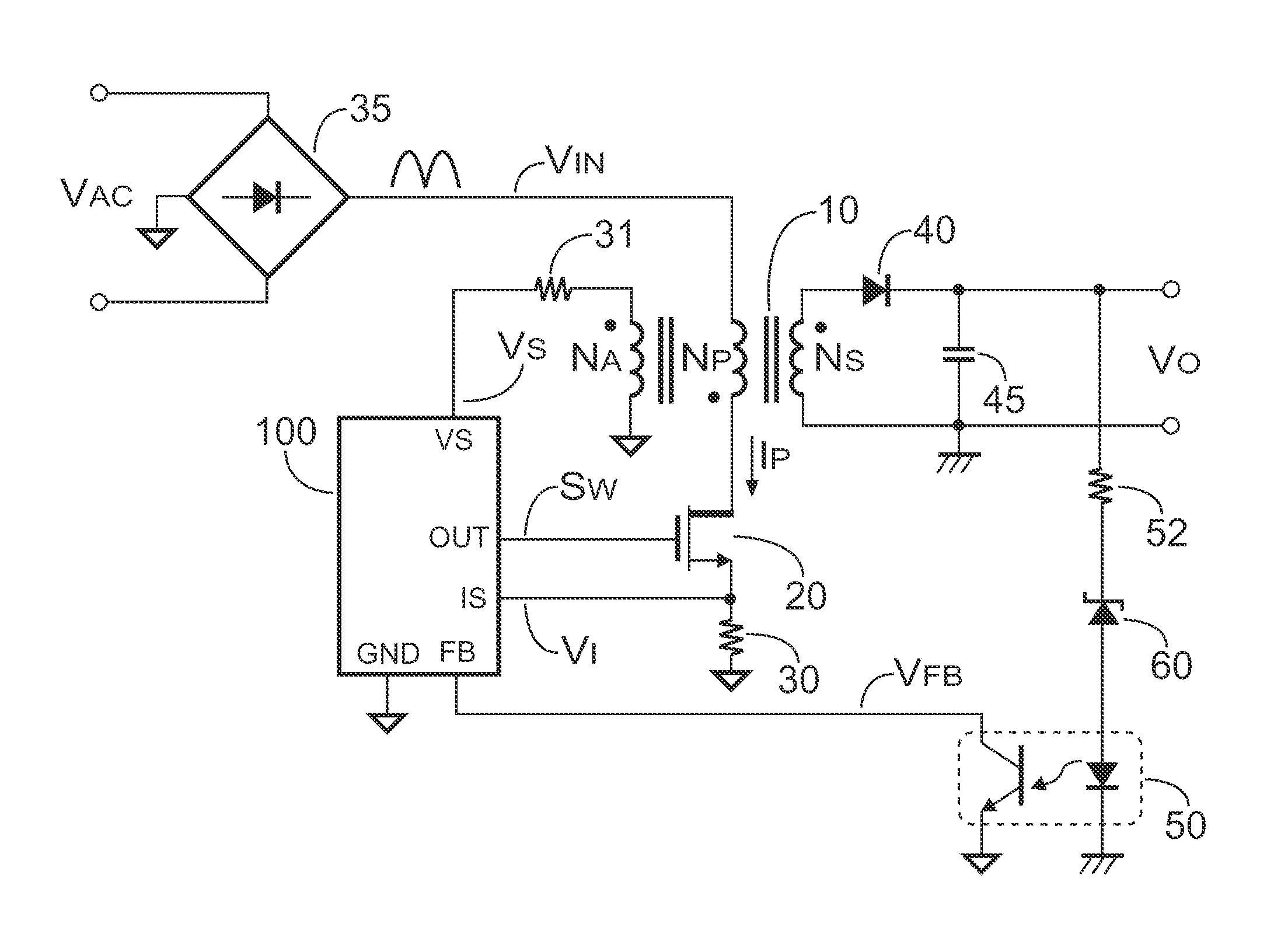
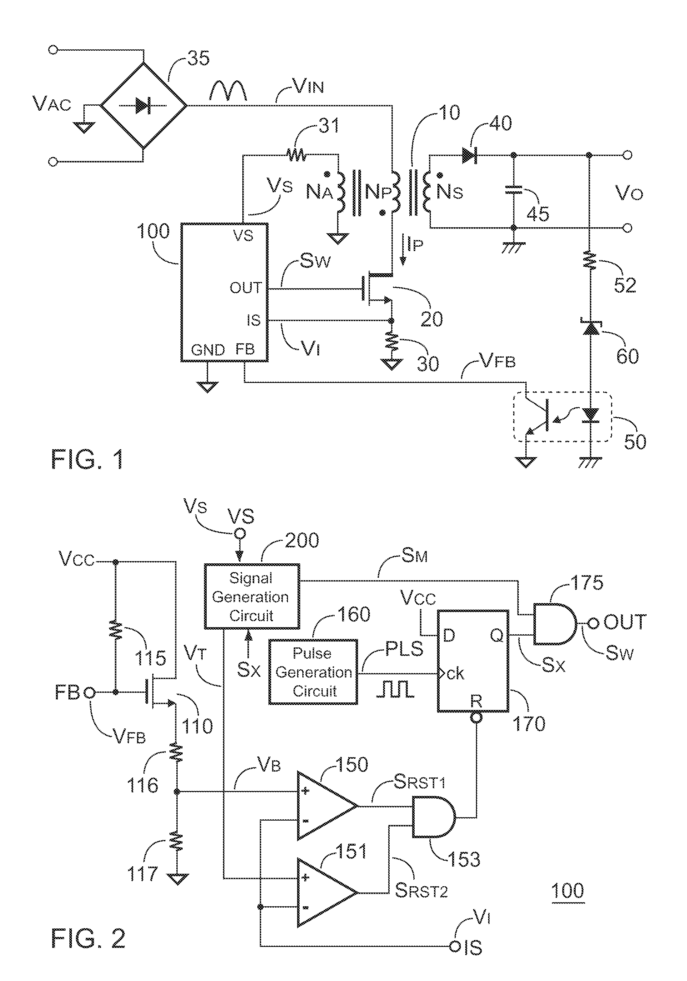
[0018]FIG. 1 shows an offline power converter without a bulk capacitor, such as an electrolytic capacitor, connected to its input. The power converter comprises a bridge rectifier 35, a transformer 10 having a primary winding NP, a secondary winding NS and an auxiliary winding NA, a power switch 20, a sensing resistor 30, a controller 100, a detection resistor 31, a rectifier 40, an output capacitor 45 and a feedback circuit. The feedback circuit comprises a resistor 52, a voltage regulator (zener diode) 60 and an opto-coupler 50. The bridge rectifier 35 converts an AC input voltage VAC to a DC input voltage VIN. The control circuit 100 generates a switching signal SW ...


PUM


Abstract

The present invention provides a control circuit for a power converter. The control circuit includes a switching circuit, an input-voltage detection circuit and a current-limit threshold. The switching circuit generates a switching signal coupled to switch a transformer of the power converter for regulating an output of the power converter in response to a feedback signal. The input-voltage detection circuit generates a control signal when an input voltage of the power converter is lower than a low-input threshold. The feedback signal is generated in response to the output of the power converter. A maximum duty of the switching signal is increased in response to the control signal. The current-limit threshold is for limiting a maximum value of a switching current flowing through the transformer. The current-limit threshold is increased in response to the control signal. An input of the power converter doesn't connect with electrolytic bulk capacitors.

Description

CROSS REFERENCE TO RELATED APPLICATIONS[0001]This application claims the benefit of U.S. Provisional Application No. 61 / 547,989, filed on Oct. 17, 2011, the contents of which are incorporated herein by reference.BACKGROUND OF THE INVENTION[0002]1. Field of the Invention[0003]The present invention relates to an offline power converter, more specifically, the present invention relates to a control circuit of the offline power converter.[0004]2. Description of the Related Art[0005]In conventional offline power converters, a bridge rectifier is utilized to rectify an AC (alternating current) input voltage into a pulsating DC (direct current) input voltage. An input capacitor, such as an electrolytic bulk capacitor, is usually applied at an output of the bridge rectifier to filter the pulsating DC input voltage as a smoother input voltage with small ripple. This bulk capacitor is utilized to store the energy and provide a minimum input voltage to guarantee a proper operation of the offli...

Claims


Application Information

Patent Timeline
IPC IPC(8): H02M3/335
CPCH02M1/4258H02M3/33507Y02B70/126Y02B70/10
Inventor YANG, TA-YUNGHSIEH, CHIH-HSIENCHEN, JUNG-SHENG
Owner SEMICON COMPONENTS IND LLC
Features
  • Generate Ideas
  • Intellectual Property
  • Life Sciences
  • Materials
  • Tech Scout
  • Unparalleled Data Quality
  • Higher Quality Content
  • 60% Fewer Hallucinations
Learn More