Wound filling apparatuses and methods

a filling apparatus and wound technology, applied in the field of wound filling apparatuses and methods, can solve the problems of affecting the healing effect of wounds, the actual form of gauze as it is packed into wounds is very variable, and patients, so as to achieve the effect of reducing the damage and trauma of wounds, facilitating healing, and facilitating healing

Inactive Publication Date: 2013-04-18
SMITH & NEPHEW INC
View PDF31 Cites 96 Cited by
  • Summary
  • Abstract
  • Description
  • Claims
  • Application Information

AI Technical Summary

Benefits of technology

[0114]The resiliently compressible wound filler may be any suitable porous material such as foam, mesh material, knitted material, corrugated material, for example, and relatively very large pore sizes up to about 10 mm may be employed. Larger pore sizes may be used but there is a limit imposed where the adhesive film may be pulled into the pores by negative pressure effect and may stick to the porous material. However, this latter problem may be overcome by interposing a sheet of a suitable material between the resiliently compressible wound packing material and the second flexible wound covering and sealing material. Suitable materials may include polyethylene and polyvinyl acetate, for example.
[0115]The second conduit may be placed adjacent the resiliently compressible wound packing material and the second layer of flexible, adhesive coated sealing material put in place to create the second sealed cavity. The second sealed cavity is isolated from the wound and is present to work or stress the wound tissue for its beneficial effect thereon. The second conduit may be connected to suitable pump means to apply a positive pressure (relative to atmospheric) and/or a negative pressure to the second sealed cavity. In most of the prior art which shows bag members or bladders, they are employed to work or stress the tissue in the wound region by inflation thereof and cycling and/or pulsing, for example, of the pressure within the bladder in a number of different ways. However, none of the bladders shown in the prior art possess the resiliently compressible wound filler illustrated in certai

Problems solved by technology

Aside from complicated and expensive inflatable bags, most of the fillers in use are based either on foam or on cotton gauze.
However both foams and gauzes have the disadvantage that the cell or pore size is often too large and often results in growing tissue growing into the cells and adhering the foam to the wound causing further damage and trauma to the wound and patient on removal.
When gauze is used as a filler, however, clinicians are instructed to “fluff up” the gauze to increase its volume which can cause problems in that the actual form of the gauze as packed into wounds is very variable.
A further disadvantage with both foams and gauze when cut to fit wounds is that of debris.
Gauze and foam are particularly prone to shedding fibres and particles when cut and these inevitably find their way into the wound and become occluded therein which can lead to later infection.
Foam or

Method used


Image

  • Wound filling apparatuses and methods
  • Wound filling apparatuses and methods
  • Wound filling apparatuses and methods

Examples


Embodiment Construction

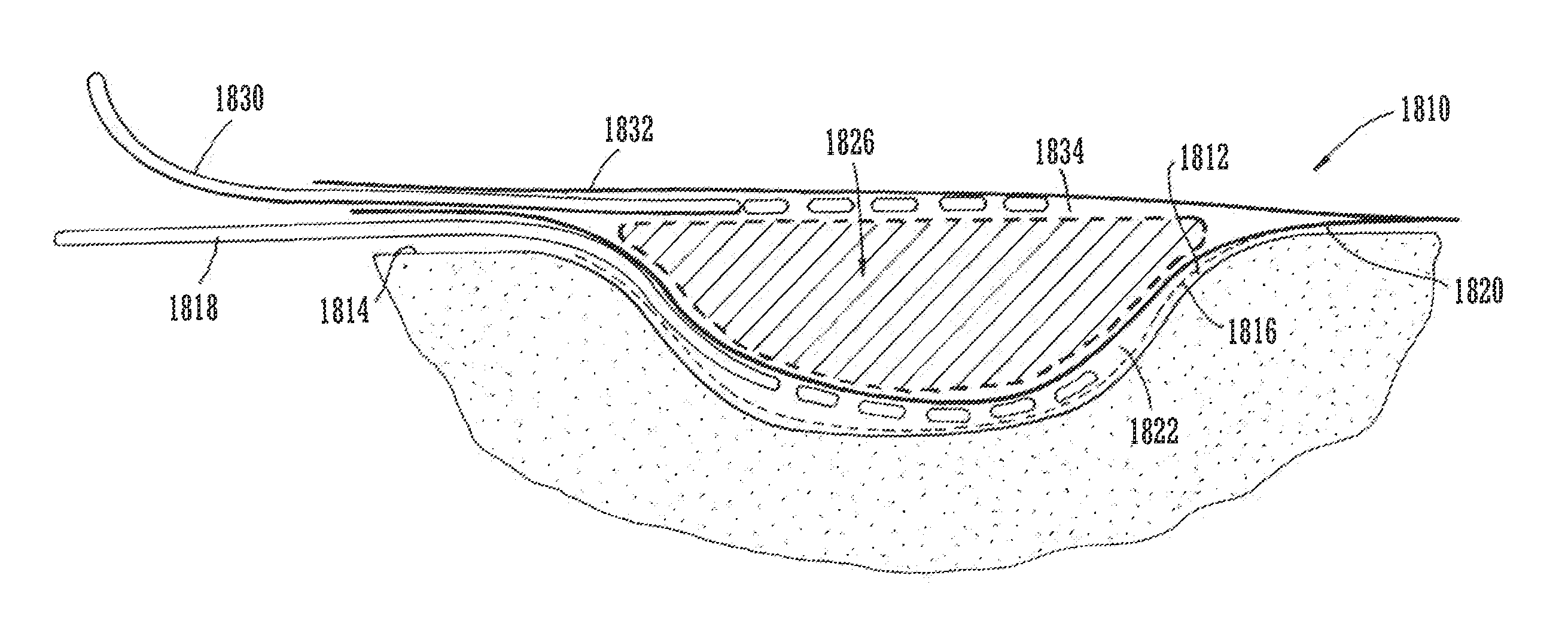
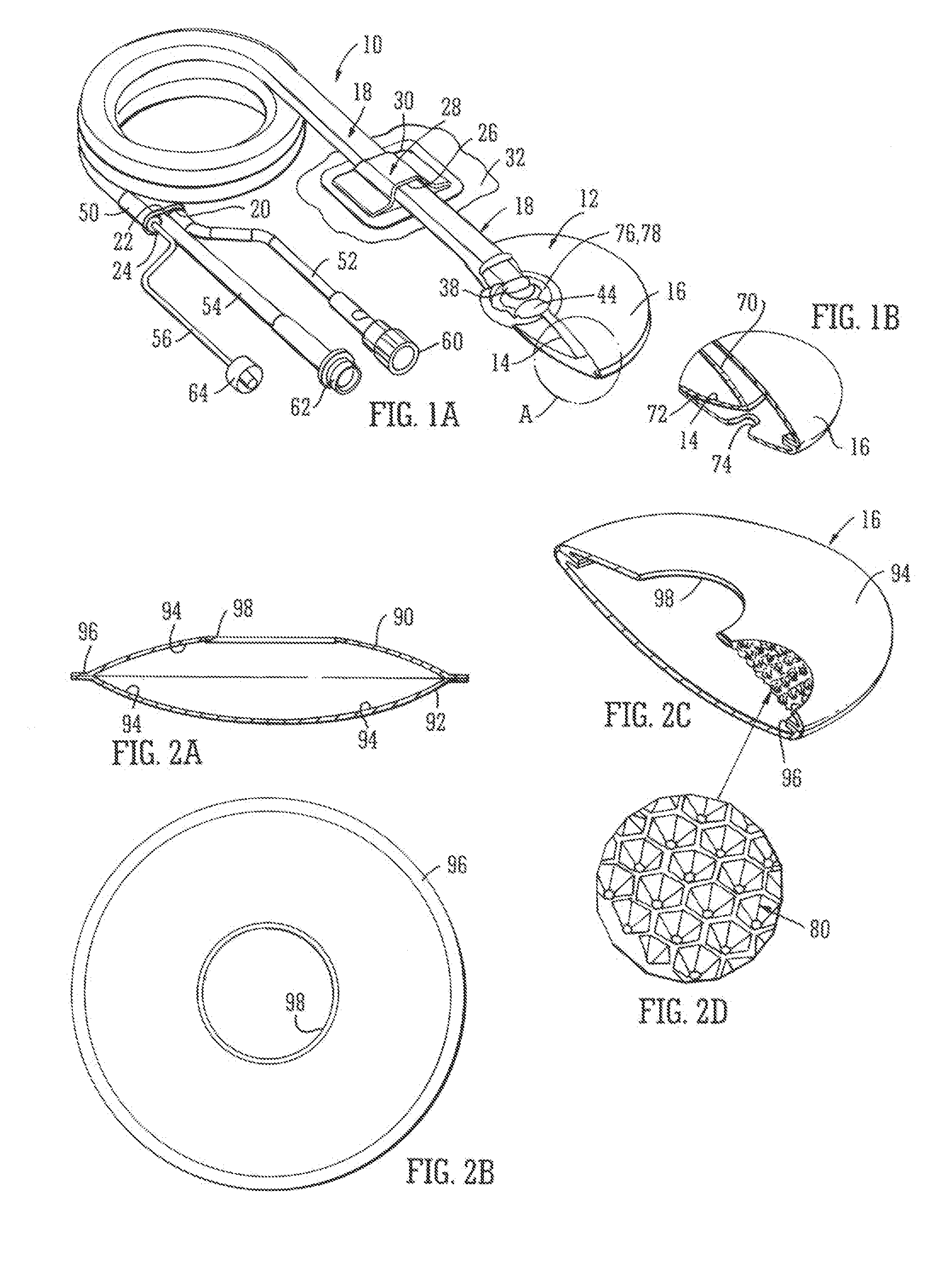
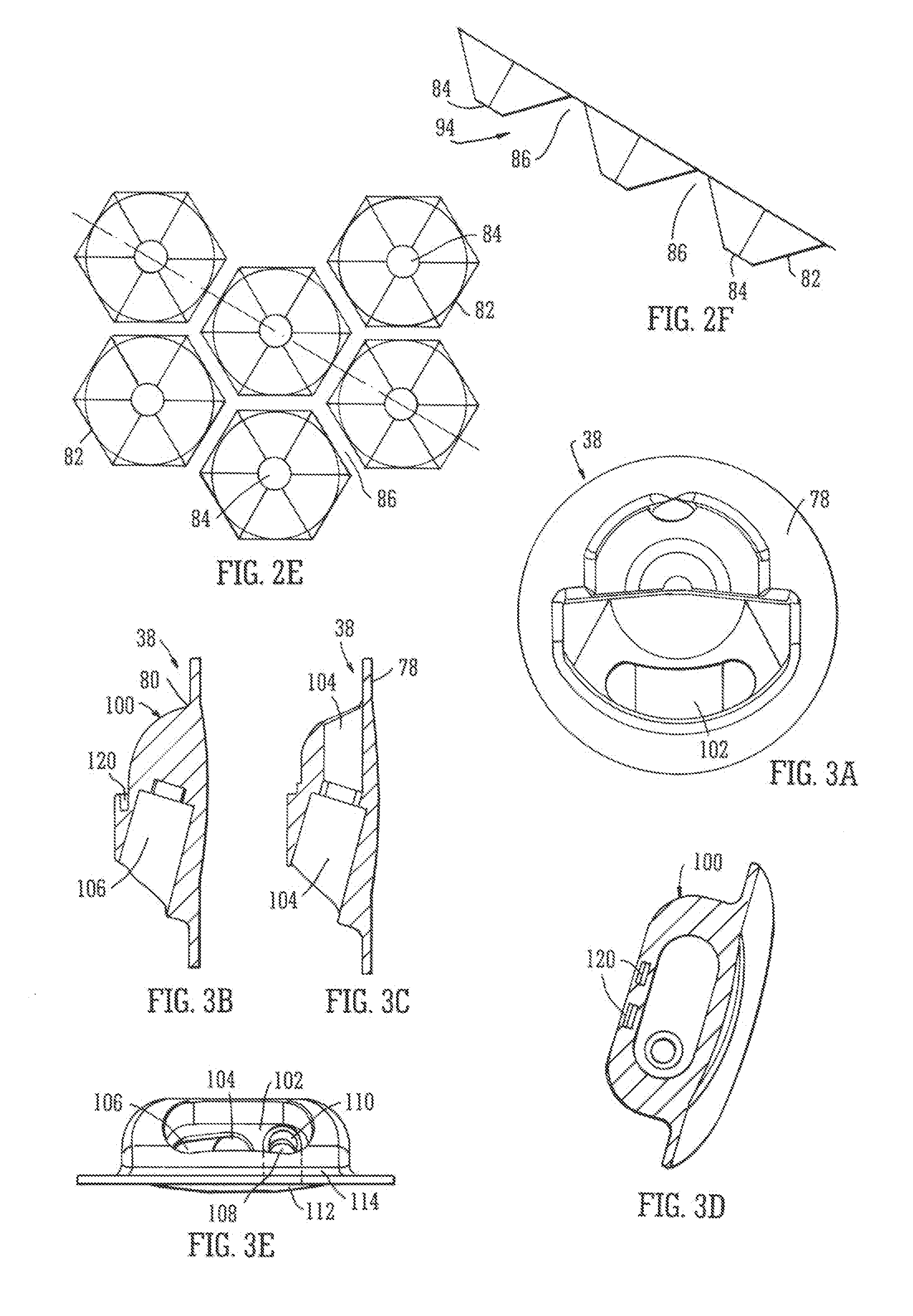
[0149]Referring now to the drawings and where the same features are denoted by common reference numerals, FIGS. 1A and 1B show a perspective view of one embodiment of a device 10 and FIG. 5 shows a schematic cross section of the device installed in a wound cavity. The device comprises a wound filling inflatable device 12 which may comprise an inflatable bag member 14 and a sock member 16. The inflatable wound filling device 12 is shown in FIG. 1 part sectioned and a detail “A” is shown at a greater magnification in FIG. 1B. The device also comprises a multi-lumen conduit 18 (shown coiled up prior to use) having three separate lumens 20, 22, 24 therethrough. The conduit 18 passes through a hole 26 in a grommet member 28 which itself is adhered by a flange 30 around the periphery of the grommet member 28 to a dressing 32 which is shown in part only and which adheres the grommet 28 to a patients' skin 34 (FIG. 5) adjacent a wound 36 to which TNP therapy is to be applied. The arrangemen...


PUM


Abstract

Many embodiments of wound filling devices and methods of their use in systems for the application of negative pressure therapy are described herein. In one embodiment, a wound filling device comprises: an inflatable bag member having at least one fluid carrying conduit operably connected thereto to inflate/deflate said bag member; a separate textured covering sock member at least partially covering the inflatable bag member. Another embodiment comprises a three-dimensional wound packing member, and may optionally comprise a plurality of such members linked together. Certain embodiments of wound packing members may comprise a porous bag member adapted to be non-adherent to the wound. Yet other embodiments may comprise a non-porous bag member provided with means to connect a fluid supply to the interior.

Description

CROSS-REFERENCE TO RELATED APPLICATIONS[0001]This application is a continuation-in-part of U.S. application Ser. No. 12 / 746,504, filed Jun. 4, 2010, which is a U.S. National Phase of PCT International Application No. PCT / GB2008 / 051114, filed on Nov. 26, 2008, designating the United States and published on Jun. 11, 2009 as WO 2009 / 071932, which claims priority to Great Britain Patent Application No. 0723874.4, filed Dec. 6, 2007. This application is also a continuation-in-part of U.S. application Ser. No. 12 / 746,508, filed Jun. 4, 2010, which is a U.S. National Phase of PCT International Application No. PCT / GB2008 / 051122, filed on Nov. 26, 2008, designating the United States and published on Jun. 11, 2009 as WO 2009 / 071935, which claims priority to Great Britain Patent Application No. 0723852.0, filed Dec. 6, 2007. This application is also a continuation-in-part of U.S. application Ser. No. 12 / 746,757, filed Jun. 7, 2010, which is a U.S. National Phase of PCT International Applicatio...

Claims


Application Information

Patent Timeline
IPC IPC(8): A61M1/00
CPCA61M1/0023A61F13/00068A61M2205/366A61M1/0088A61M2205/3606A61F13/0216A61M1/92A61M1/915A61M1/71
Inventor HALL, KRISTIANHARTWELL, EDWARDNICOLINI, DEREK
Owner SMITH & NEPHEW INC
Why Eureka
Try Eureka