Heating system utilizing microwave

a heating system and microwave technology, applied in muffle furnaces, lighting and heating apparatus, furnaces, etc., can solve the problems of loss of heat energy, ineffective heating of raw fibers in heating furnaces, and insufficient heat loss of filling density, so as to improve heat flow at the end of heating ovens, improve filtering effect, and improve energy saving

Inactive Publication Date: 2013-04-25
MICRO DENSHI +1
View PDF8 Cites 25 Cited by
  • Summary
  • Abstract
  • Description
  • Claims
  • Application Information

AI Technical Summary

Benefits of technology

[0093]As in the ninth aspect of the invention, the filtering zones may be respectively provided with microwave heat generating means to assure that the filtering effect is improved and simultaneously heat flow at the ends of the heating oven is also improved. In this way, the heating oven can be efficiently kept at the desired high temperature, leak of the microwave power potentially occurring at the inlet and the outlet of the heating furnace main body can be prevented and the energy saving effect is also improved.

Problems solved by technology

Specifically, the portion of the heat energy which can contribute to heat the heating oven is limited to a range defined by a solid angle covering the heating oven and the rest is the loss of the heat energy.
For such conventional heating furnace, when the individual raw fibers, for example, 12,000 raw fibers arranged side by side in the transverse direction without use of the container are transported through the furnace, a filling density will be too low to heat the raw fibers within the heating furnace effectively.

Method used


Image

  • Heating system utilizing microwave
  • Heating system utilizing microwave
  • Heating system utilizing microwave

Examples


first embodiment

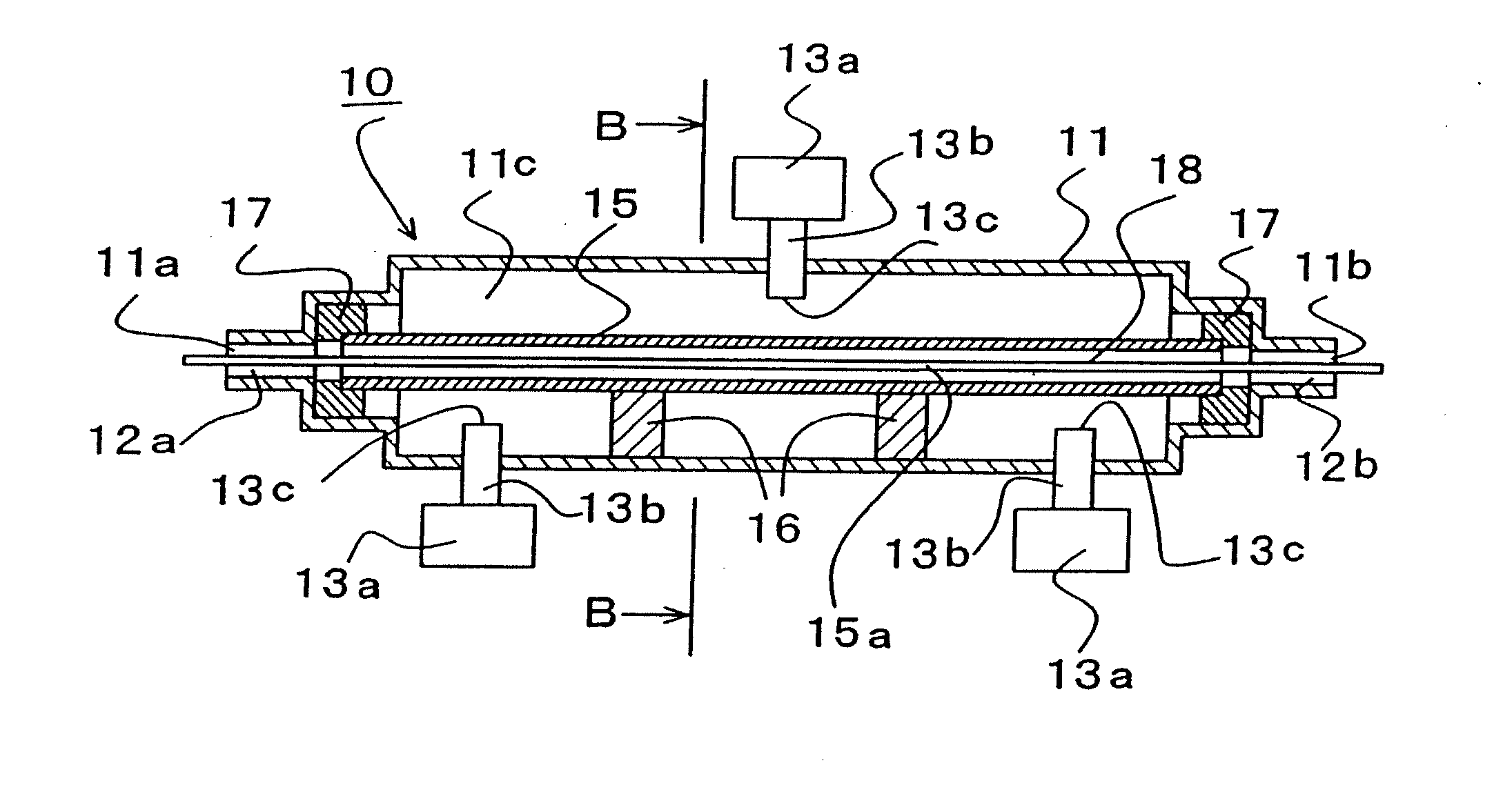
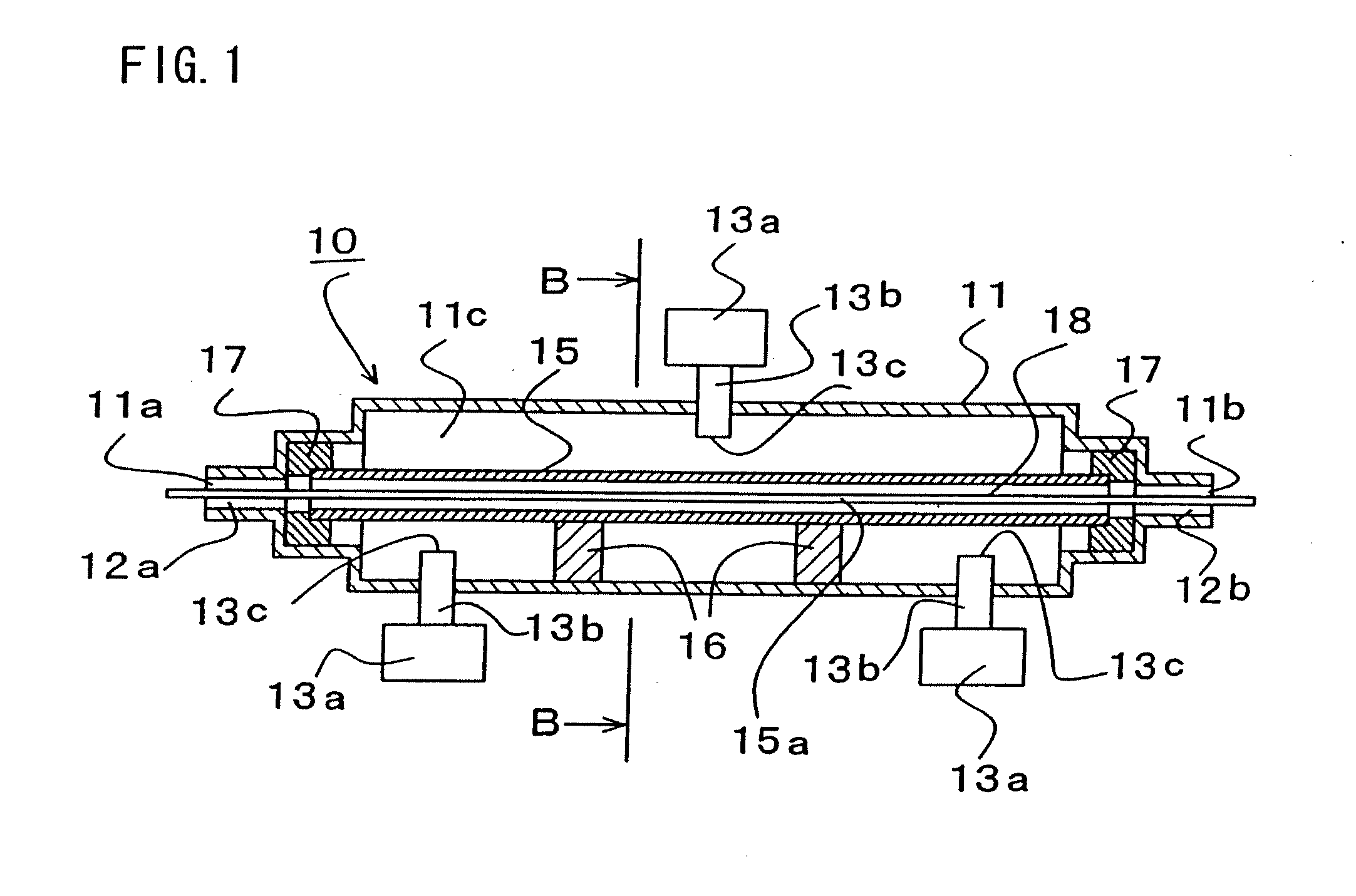
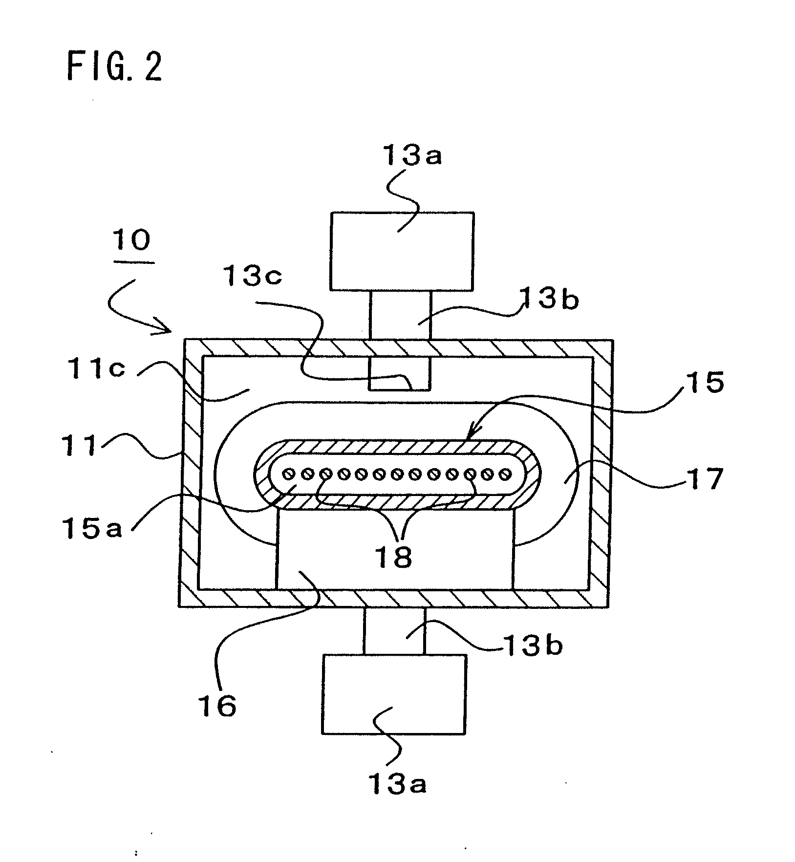
[0116]FIG. 1 is a sectional view of heating system according to this invention taken along a plane extending in parallel to a direction in which a work is transported and FIG. 2 is a scale-enlarged sectional view taken along a line B-B in FIG. 1.

[0117]As will be apparent from FIGS. 1 and 2, the heating system 10 according to this embodiment includes a heat furnace main body 11 and a microwave supplying means adapted to supply microwave power into this heating furnace main body.

[0118]The heating furnace main body 11 is made of nonmagnetic metallic material in the form of a transversely long box and provided on one side in the longitudinal direction with an inlet 11a and on the opposite side with an outlet 11b.

[0119]In the vicinity of these inlet 11a and outlet 11b, filtering zones 12a, 12b are provided so as to prevent microwave power from leaking.

[0120]These filtering zones 12a, 12b utilize a choke structure to block passage of the microwave power and thereby to prevent the microwa...

second embodiment

[0155]FIG. 11 illustrates the heating system 30 as one of modified embodiments of the second embodiment wherein the heating oven 15 is provided on the outer surface thereof with the heat insulator 20 having low microwave absorption ability as the heating system illustrated in FIG. 4 is the case.

[0156]FIG. 12 illustrates the heating system 30 as one of modified embodiments of the second embodiment provided with the heating oven 15 of three-layered construction including the inner layer 21 made of the microwave shielding material, the intermediate layer 22 made of the microwave heat generating material and the outer layer 23 made of the heat insulator material having low microwave absorption ability as the heating system illustrated in FIGS. 6 and 7 is the case.

[0157]FIG. 13 illustrates the heating system 30 similar to that illustrated in FIG. 12 except that the heating oven 15 is partially provided with the intermediate layer 22 made of the microwave heat generating material.

[0158]FI...


PUM

PropertyMeasurementUnit
temperatureaaaaaaaaaa

Abstract

This present invention provides a heating system utilizing microwave energy for an improved manufacture of high quality fibers such as carbon fiber and graphitic fiber while simultaneously simplifying construction and meeting a demand for saving electric energy.

Description

[0001]This application claims priority to JP application 2011-136276, filed on Jun. 20, 2011, which is herein incorporated by reference in its entirety.BACKGROUND OF THE INVENTION[0002]This invention relates to a heating system utilizing microwave energy and particularly to the heating system suitable as a heating furnace used to manufacture, for embodiment, carbon fiber or graphitic fiber.Background Art[0003]The carbon fiber is usually manufactured by the process including steps of heat-treating (flame-proofing) organic synthetic fibers such as polyacrylonitrile (PAN) in air at a temperature in a range of 200 to 300° C. with use of a flame-proofing furnace to produce string-like flame resistant fibers preliminarily and heat-treating the flame resistant fibers in inert atmosphere at a temperature in a range of 1000 to 1500° C. with use of a carbonizing furnace.[0004]The carbon fiber manufactured in this manner is used as material for parts of car.[0005]The aforementioned carbon fibe...

Claims


Application Information

Patent Timeline
Patent Type & Authority Applications(United States)
IPC IPC(8): H05B6/64
CPCD01F9/32F27D11/12F27B5/14F27B5/04H05B6/64H05B6/80
Inventor HARADA, AKIKAZUKANDA, KIICHIWATANABE, KEN-ICHISAKAMOTO, NATSUMITAKAHASHI, SHIN-ICHI
Owner MICRO DENSHI
Why Eureka
Try Eureka