
Motor control method and motor control apparatus for dental handpiece

a motor control and handpiece technology, applied in the direction of electric motor control, dental surgery, dental tools, etc., can solve the problems of motor control apparatus inferior to feedback control in cutting efficiency, excessive torque applied to cutting tools, and the cutting tool can be broken or jammed into the root canal, so as to prevent excessive load torque, reduce torque gradually, and prevent the effect of cutting tools from being broken

Inactive Publication Date: 2013-04-25
NAKANISHI INC
View PDF4 Cites 15 Cited by
  • Summary
  • Abstract
  • Description
  • Claims
  • Application Information

AI Technical Summary

Benefits of technology

The present invention relates to a control method for a motor used in a cutting tool. The control method limits the motor current to a first limit current, which stops the rotation of the motor when the load torque (the force applied to the cutting tool) increases, preventing the tool from being broken. Even when the motor is stopped, the first limit current is still applied, preventing any sudden drop in torque. Additionally, when the load torque decreases, the motor current is controlled to equal or decrease to a second limit current, which is lower than the first limit current, to prevent torque drop and alleviate discomfort to the patient and operator. The control method gradually reduces the motor current after the rotation of the motor is stopped, reducing discomfort. Overall, the control method ensures safe and efficient use of the motor in a cutting tool.

Problems solved by technology

However, when the feedback control is used for root canal formation or other operations that involve using a thin cutting tool that is easily broken, there arises an operational problem that an excessive torque can be applied to the cutting tool, and the cutting tool can be broken or jammed into a root canal.
However, although the motor control apparatus disclosed in Japanese Patent No. 3264607 can prevent the cutting tool from being broken or jammed into a root canal, the motor control apparatus is inferior to the feedback control in cutting efficiency because the rotational speed of the cutting tool decreases as the load torque increases.
As a result, the torque of the motor (the cutting tool) in the direction of rotation suddenly drops, thereby causing a shock (referred to as discomfort hereinafter) to the patient and the operator.

Method used


Image

  • Motor control method and motor control apparatus for dental handpiece
  • Motor control method and motor control apparatus for dental handpiece
  • Motor control method and motor control apparatus for dental handpiece

Examples


Embodiment Construction

[0037]In the following, the present invention will be described in detail with regard to an embodiment shown in the accompanying drawings.

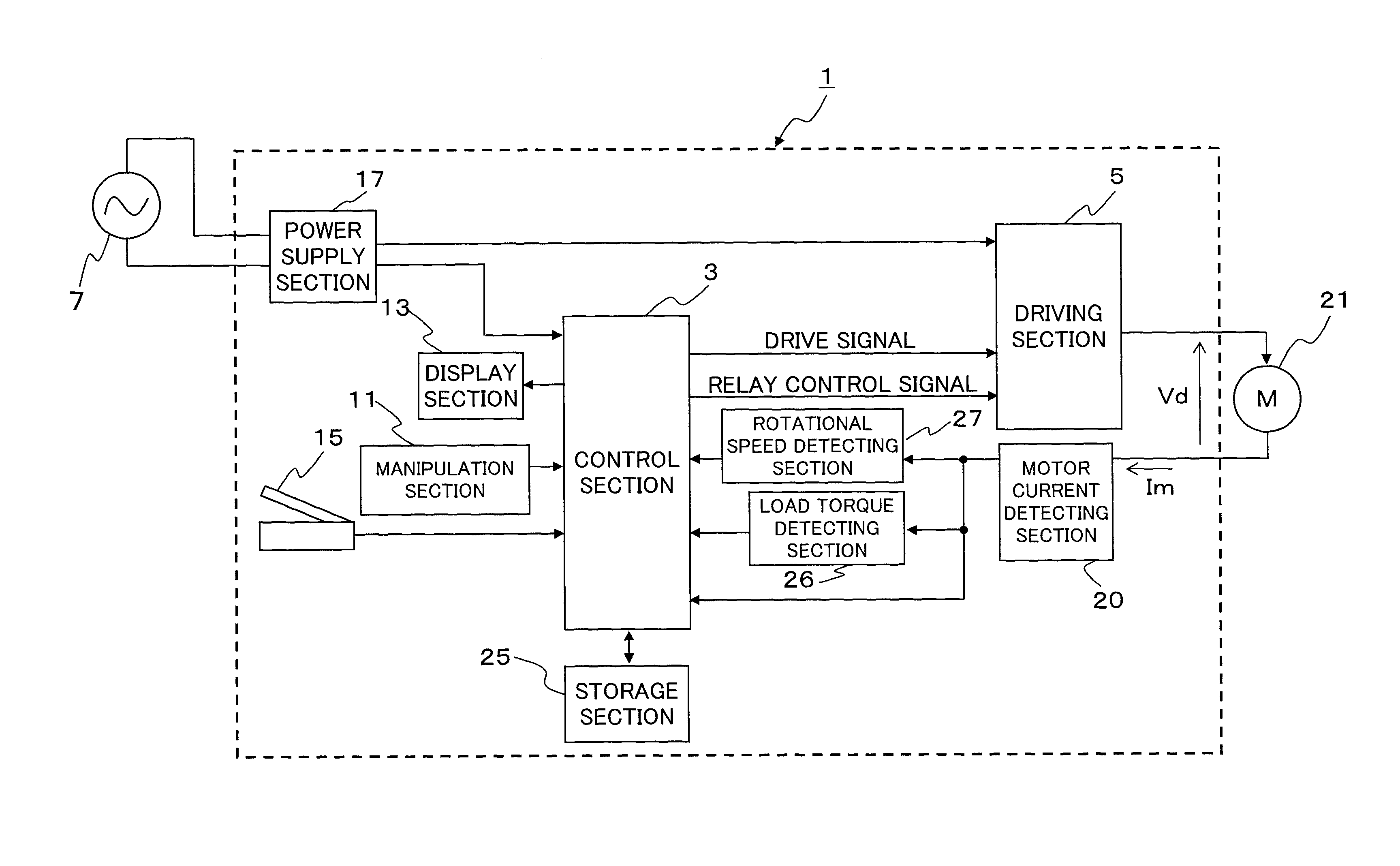
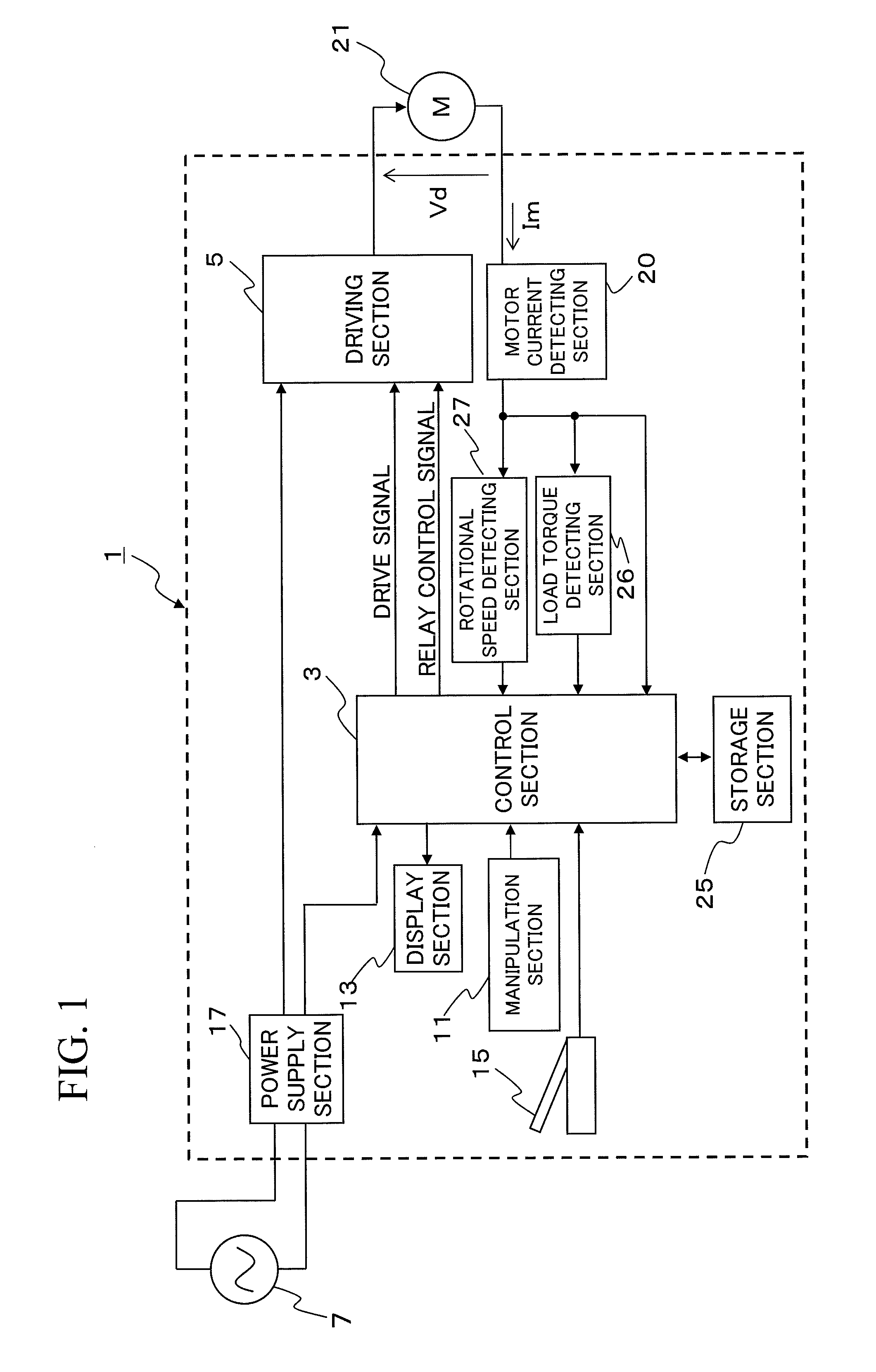
[0038]A motor control apparatus 1 according to the embodiment shown in FIG. 1 controls a motor 21, which is a three-phase brushless motor incorporated in a dental handpiece. The motor control apparatus 1 comprises a control section 3, a storage section 25, a driving section 5, a manipulation section 11, a display section 13, a foot pedal 15, a motor current detecting section 20, a rotational speed detecting section 27, a load torque detecting section 26, and a power supply section 17.

[0039]According to this embodiment, the motor 21 is driven by a pulse width modulation (PWM) driving scheme, and a PWM signal generated by the control section 3 controls the driving section 5 to supply a driving voltage to the motor 21.

[0040]In the following description, the direction of rotation of the motor 21 to cut teeth will be referred to as a forward direction,...


PUM


Abstract

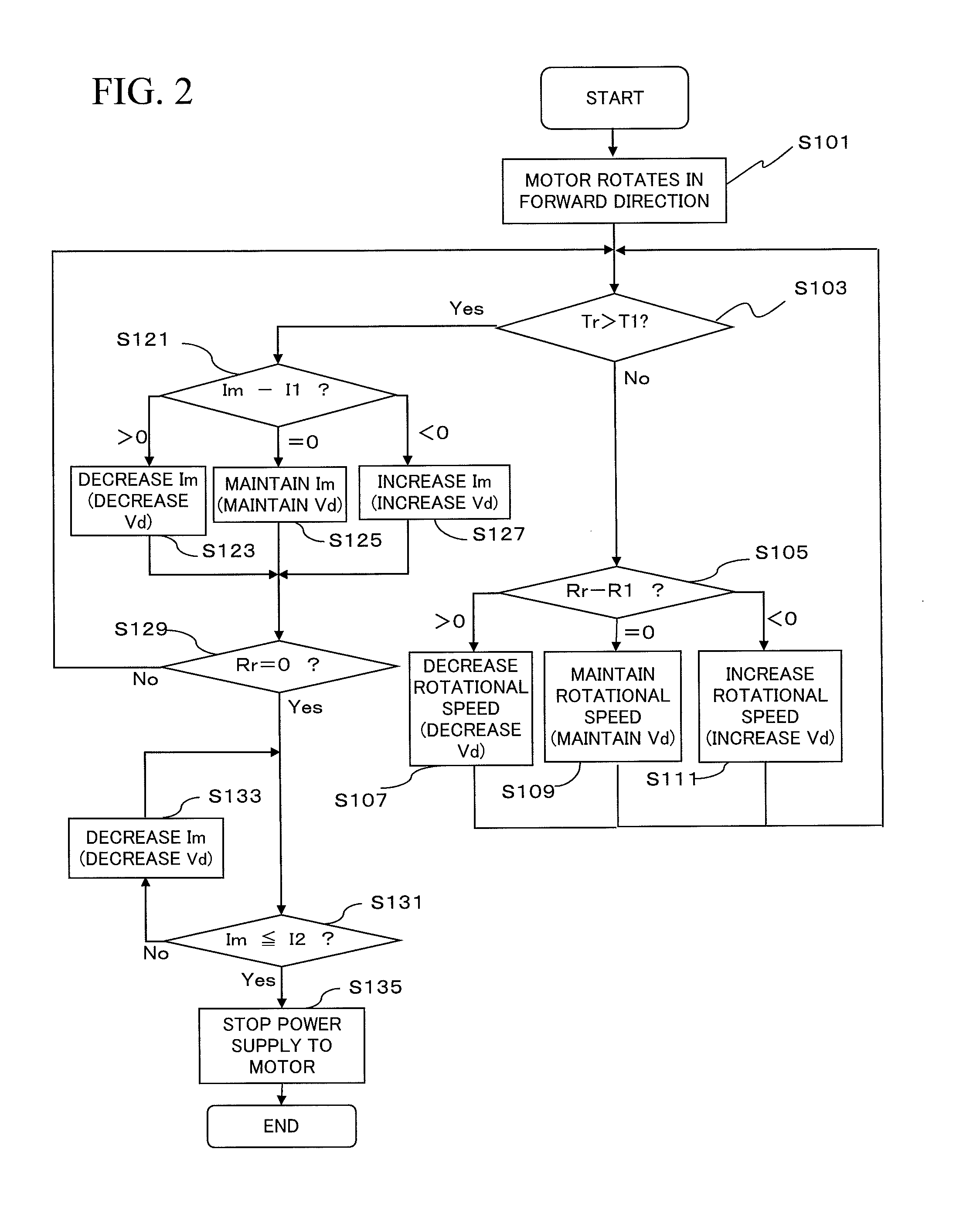
The present invention relates to a motor control method for a dental handpiece provided with a motor that rotationally drives a cutting tool. The control method includes a step A of limiting the motor current to a first limit current I1 when the load torque applied to the cutting tool exceeds a preset limit torque value, and a step B of controlling the motor current to be equal to or lower than a second limit current, which is lower than the first limit current, when it is detected that the motor stops rotating.

Description

BACKGROUND OF THE INVENTION[0001]1. Field of the Invention[0002]The present invention relates to a motor control method and a motor control apparatus for a dental handpiece that cuts teeth or forms a root canal with a cutting tool.[0003]2. Description of the Related Art[0004]To cut teeth or form a root canal, a dental handpiece provided with an electrical motor as a driving source is used. The operator selects one suitable for the operation from among a plurality of types of cutting tools.[0005]A known method of controlling the motor of such a dental handpiece is a feedback control, in which the motor is controlled so as to keep the preset rotational speed by detecting the rotational speed of the motor and increasing or decreasing the motor driving voltage based on the detected rotational speed.[0006]If the load torque on the cutting tool increases and the rotational speed decreases, a motor control apparatus based on the feedback control increases the motor driving voltage, thereby...

Claims


Application Information

Patent Timeline
Patent Type & Authority Applications(United States)
IPC IPC(8): H02P29/02A61C1/06
CPCA61C1/0015H02P29/027A61C1/186A61C1/06A61C1/08A61C3/02
Inventor OKAMOTO, HIDEKI
Owner NAKANISHI INC
Learn More