System for determining the distance from and the direction to an object

a technology of distance estimation and direction, applied in the field of system and a method for determining the distance from and the direction to an object, can solve the problems of ambiguity in the distance estimation and position, the transmission and/or reception characteristics of an individual sensor are often so greatly limited, and the transmission and/or reception characteristics must be greatly limited, so as to improve the near-field detection effect and increase the detection tim

Active Publication Date: 2013-04-25
ROBERT BOSCH GMBH
View PDF3 Cites 15 Cited by
  • Summary
  • Abstract
  • Description
  • Claims
  • Application Information

AI Technical Summary

Benefits of technology

[0034]In an active method for determining the distance from and the direction to an object, an array composed of multiple emitter elements and at least one separate receiver is used. This system allows perception of objects from a distance of 0 cm and greater. For obstacle detection, however, the entire surroundings must be scanned, thus increasing the detection time as a function of the grid resolution, even if tracking for the position determination is dispensed with.
[0035]In contrast, for a passive ultrasonic array a signal is emitted by at least one emitter and received by a receiver array. It is thus possible to detect signal-reflecting obstacles for the entire surroundings, using only one transmitted ultrasonic pulse. This design according to the present invention of the separate emitters and receiver elements once again has the advantage of improved near-field detection, but also allows the task-specific dimensioning of the emitters and receiver elements.

Problems solved by technology

The disadvantages of the trilateration methods lie essentially in the problem with assignment, and thus, the ambiguity in the distance estimation and position when there are multiple reflectors in the scene.
Alternatively, the transmission and / or reception characteristics of an individual sensor are often so greatly limited that the detection range of the sensor allows the lateral or vertical positioning of an obstacle.
In this case it is disadvantageous that the transmission and / or reception characteristics must be greatly limited in order to achieve position accuracies which are relevant in practice, so that a large number of sensors is necessary for monitoring the detection range.
In most beamforming methods, the element spacing should be less than or equal to one-half the wavelength of the signal, since otherwise, so-called grating lobes, i.e., side lobes in the transmission or reception characteristics on the order of magnitude of the main lobe, may appear which may result in ambiguities in the detection.
As a result of the element spacing being less than or equal to one-half the wavelength of the signal, the size of the usable array elements is limited.
Due to the poor coupling of the emitters and receivers to the medium air, large emitter surface areas in the case of emitters, or small masses / large surface areas in the case of receivers, are required.
However, large surface areas for individual array elements are not achievable due to the required small element spacing between the array elements.
However, the receivers are only conditionally suited for application in the automotive field, since the described thin film piezoelectric emitter is susceptible to mechanical strain.
Therefore, it is assumed that the sensor described in U.S. Patent Application Publication 2008 / 0165620 is not suited for beamforming methods.
A disadvantage of the method described in French patent document 2 817 973 is that a homogeneous linear array is assumed, and in particular the function of transmission is not separated from the function of reception.
Although this patent describes an active beamforming, the large emitter surface as well as the narrow emitter characteristic conflicts with use as an active emitter array.
In addition, the two transmitting frequencies used conflict with the approach described in this claim.

Method used


Image

  • System for determining the distance from and the direction to an object
  • System for determining the distance from and the direction to an object
  • System for determining the distance from and the direction to an object

Examples


Embodiment Construction

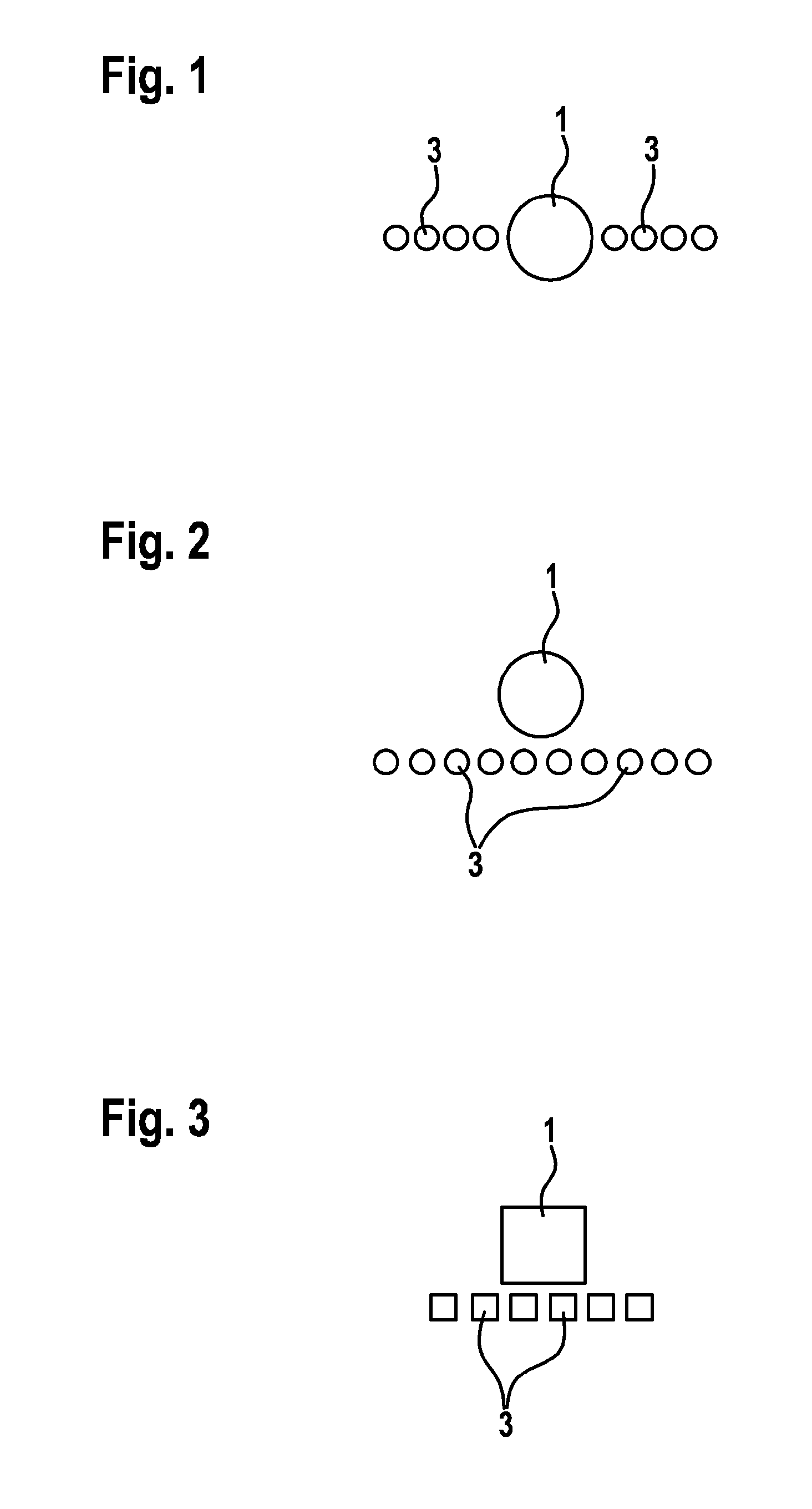
[0043]FIGS. 1 through 3 illustrate systems having an emitter and receiver elements which are arranged as a linear array. A system includes an emitter 1 and at least two receiver elements, in the specific embodiments illustrated here, eight receiver elements 3 in FIG. 1, ten receiver elements 3 in FIG. 2, and six receiver elements 3 in FIG. 3. Receiver elements 3 are arranged as a linear array, i.e., in a row next to one another. In the specific embodiment illustrated in FIG. 1, emitter 1 interrupts the array formed from receiver elements 3, and thus forms a part of the linear array.

[0044]According to the present invention, emitter 1 has a height or a diameter which is greater than one-half the wavelength of the signal. In contrast, receiver elements 3 have a height or a diameter which at most corresponds to one-half the wavelength of the signal. In the specific embodiment according to FIG. 1, emitter 1 and receiver elements 3 are designed with a circular cross section, so that in th...


PUM


Abstract

A system for determining the distance from and the direction to an object includes an emitter and at least two receiver elements for receiving a signal which is transmitted by the emitter and reflected by the object. The receiver elements are arranged as a linear array, as two linear arrays situated at an angle to one another, as an array which surrounds the emitter and forms a circle, or as a two-dimensional array. The diameter of the array may be greater than one-half the wavelength of the signal, and the receiver elements each have an individual surface area whose height or diameter corresponds at most to one-half the wavelength of the signal, and the emitter has a height or a diameter which is greater than one-half the wavelength of the signal.

Description

BACKGROUND OF THE INVENTION[0001]1. Field of the Invention[0002]The present invention is directed to a system and a method for determining the distance from and the direction to an object.[0003]2. Description of the Related Art[0004]For determining the distance from an object, sensors are usually used which emit a signal and receive an echo of the signal which is reflected by the object. The distance from the object is determined based on the propagation time of the signal from the point in time when the signal is transmitted until the echo is received.[0005]In addition to the distance from an object, the direction in which the object is located is also usually of interest. In particular for applications in the automotive field, the information concerning the direction of an object as well as the distance information are essential. Distance information and direction information for objects are also of crucial importance in robotics, for example for obstacle recognition in near-field...

Claims


Application Information

Patent Timeline
Patent Type & Authority Applications(United States)
IPC IPC(8): G01S15/93G01S15/931
CPCG01S15/931G01S2013/466G01S2015/465G01S13/46G01S15/93G01S15/88G01S13/93
Inventor BROWN, CHRISTOPHERSTREICHERT, FELIXZOTT, CHRISTIANGERLACH, ANDRE
Owner ROBERT BOSCH GMBH
Why Eureka
Try Eureka