Petri dish provided with means forming evidence of use

a technology of evidence and petri dish, which is applied in the field of petri dish, can solve the problems of false positive, inability to guarantee, and inability to guarantee security, and achieve the effects of limiting gas exchange, increasing the incubation time of the dish, and reducing the dryness of the nutritive substra

Active Publication Date: 2013-04-25
BIOMERIEUX SA
View PDF4 Cites 3 Cited by
  • Summary
  • Abstract
  • Description
  • Claims
  • Application Information

AI Technical Summary

Benefits of technology

[0007]In the case of dishes without lugs, the lid rests directly on the lower receptacle, thereby limiting gas exchanges. In this case, the dryness of the nutritive substrate is lower and thus allows the nutritive substrate to be preserved for a longer time. The absence of lugs also allows an increase in the incubation time of the dish without any dryness, thereby guaranteeing better growth of “stressed” micro-organisms or with slow growth. Certain types of Petri dishes moreover allow the dish to be closed after sampling through a locking system (a lid attached by mechanical tightening or mechanical locking by rotation or clipping) so that the dish will not open by itself in order to limit risks of subsequent contaminations after sampling.

Problems solved by technology

However, if the solutions proposed up to now allow locking of said dish in the case of a fall or tampering, it is impossible to guarantee that the dish received for cultivation has not been opened and it is therefore not possible to guarantee the security of the result and the absence of “recontamination”, in fact inducing false positive results.
By the presence of this blocking means, it is normally not possible to bring the receptacle and lid back into the preceding position.

Method used


Image

  • Petri dish provided with means forming evidence of use
  • Petri dish provided with means forming evidence of use
  • Petri dish provided with means forming evidence of use

Examples


first embodiment

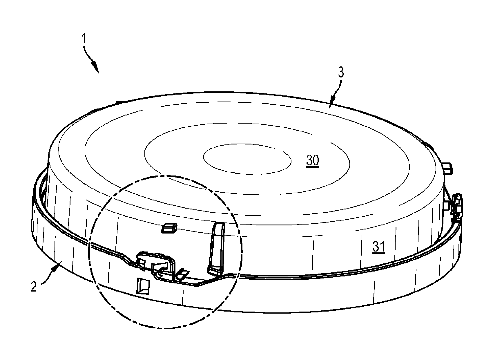
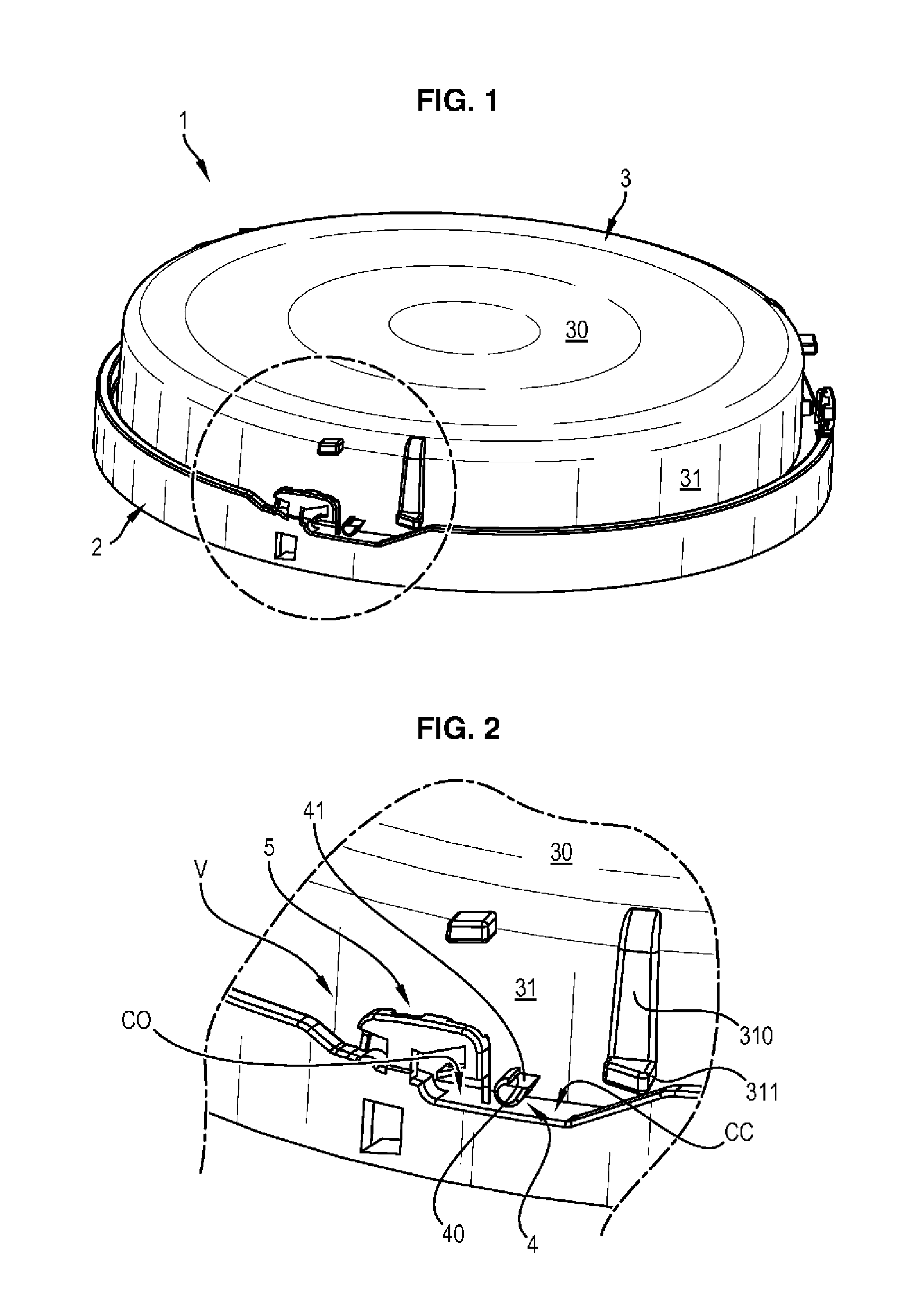
[0055]Reference will now be made to FIGS. 1 to 15 for giving details of the structure of the Petri dish according to the invention. As this is more particularly visible in FIGS. 1, 3 and 5, the Petri dish 1 consists of a receptacle 2 and of a lid 3, for example both in a transparent plastic material such as crystalline polystyrene. The receptacle 2 has a revolution shape and includes a bottom 20 with a circular contour, the upper surface of which is planar and the periphery of which is vertically delimited by a first wall 22, a so-called “inner wall”. As this is particularly visible in FIG. 3, this wall 22 has on its external face, small overthicknesses 220 which have the shape of small pillars and the function of which will be explained later on.

[0056]The bottom 20 continues radially beyond the first wall, in order to form a peripheral path 23, itself delimited by said wall 22, as well as a second wall 21, a so-called “outer wall”, with a generally cylindrical shape. This outer wal...

second embodiment

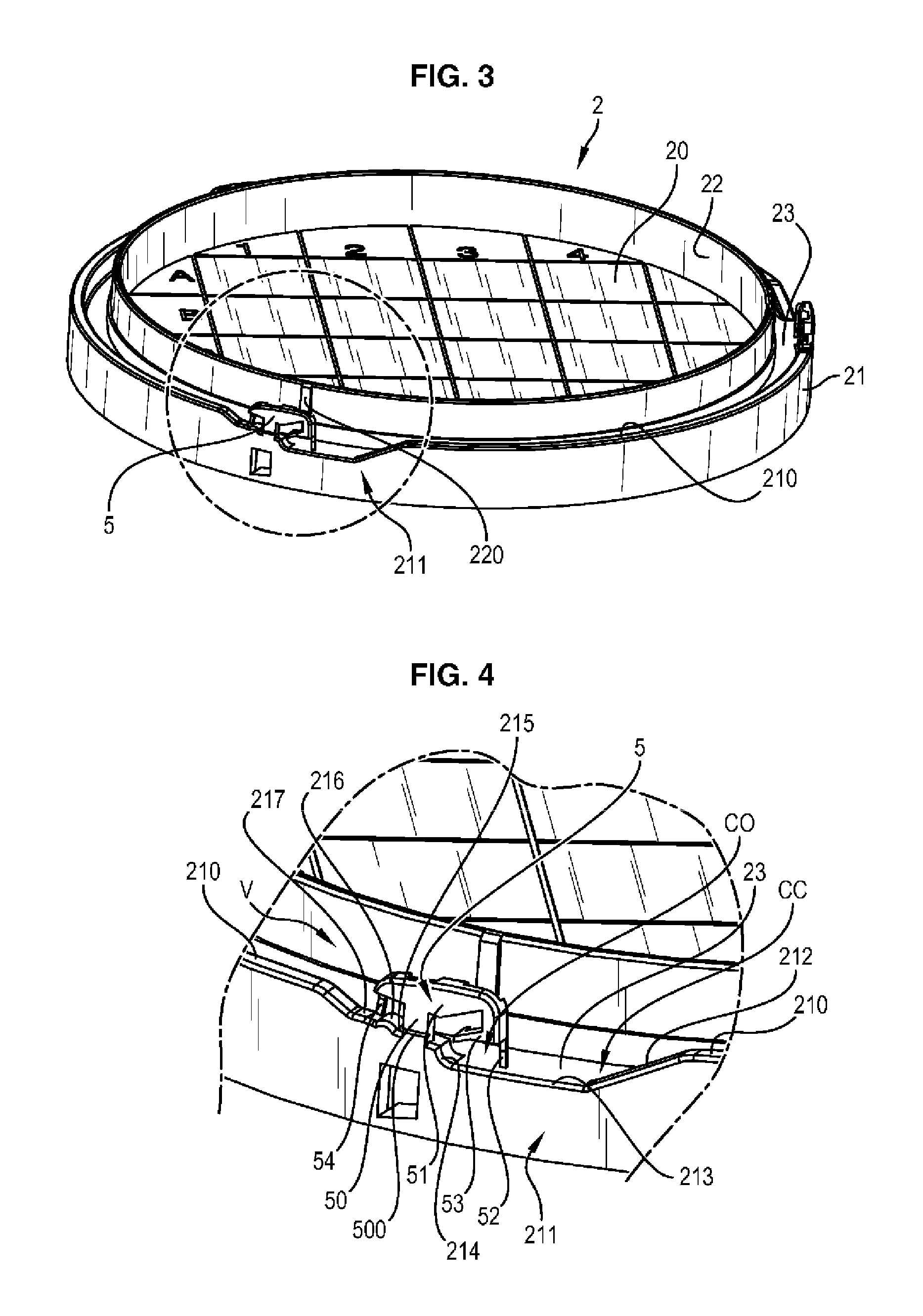
[0079]In FIGS. 16 to 23, the Petri dish is described. The latter is very close to the embodiment already described, notably as regards the structure of the receptacle 2. In this case, the bottom wall 20 is connected to two outer 21 and inner 22 cylindrical walls, separated by a ring-shaped peripheral path 23.

[0080]In three angularly equidistant areas, the outer wall 21, bears as cut-outs made in the thickness of the wall, three cam paths CC accessible through the top of the wall, via an opening O. As this is visible in FIG. 17, notably, the cam path CC is delimited upwards by a lug 5′ which is made with the wall 21 in the same material. Opposite to the aforementioned opening O, this lug 5′ has a partial cut-out 8 and only holds on to the remainder of the wall through a small material strip referenced as80. As this is further shown by this figure, this receptacle includes a blocking means as an anti-return ratchet 7, which is not integrated within the lug 5′ like in the first embodim...


PUM

PropertyMeasurementUnit
diametersaaaaaaaaaa
interior angleaaaaaaaaaa
relative displacementaaaaaaaaaa

Abstract

A Petri dish includes a receptacle and a matching lid, which both have a shape of revolution and are each delimited by a bottom wall and at least one peripheral rim. This also includes fingers and complementary locking elements. The receptacle and the lid, when rotated relative to each other, are able to occupy three or four different positions, including at least a “first position” and an “intermediate position”. This dish is distinguished by the fact that the locking elements carry at least one blocking member which blocks the fingers in the “intermediate position” and which opposes the return to the “first position”.

Description

CROSS-REFERENCE TO RELATED APPLICATIONS[0001]This application is a National Phase Entry of International Application No. PCT / EP2011 / 059366, filed on Jun. 7, 2011, which claims priority to French Patent Application Serial No. 1054957, filed on Jun. 22, 2010, both of which are incorporated by reference herein.BACKGROUND AND SUMMARY[0002]The present invention relates to a Petri dish for cultivating micro-organisms, comprising a receptacle with a revolution shape receiving a nutritive substrate and on which rests a lid. A particularity of this Petri dish, in a specific embodiment, lies in the presence of several protrusions or fingers at the periphery of the lid, and of “attachment points” at the periphery of the receptacle receiving the protrusions of the lid.[0003]The person skilled in the art in the field of techniques for microbiological analyses uses Petri dishes of different sizes for cultivating micro-organisms (diameters generally varying from 50 to 150 mm). The most common mate...

Claims


Application Information

Patent Timeline
Patent Type & Authority Applications(United States)
IPC IPC(8): C12M3/00
CPCC12M23/46C12M23/10C12M23/38
Inventor HUET, STÉPHANETHEPAUT, JÉRÔMEGINCHELEAU, CHRISTOPHESIMON, FRÉDÉRICREVERDY, FRANK
Owner BIOMERIEUX SA
Why Eureka
Try Eureka